How to Use 4 Channel Motor Controller: Examples, Pinouts, and Specs
Introduction
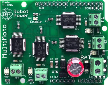
The 4 Channel Motor Controller is a versatile electronic device designed to control the speed and direction of up to four DC motors independently. It is widely used in robotics, automation systems, and other applications requiring precise motor control. This component simplifies motor management by providing an interface to adjust motor parameters such as speed and direction through external signals, such as microcontrollers or manual inputs.
Explore Projects Built with 4 Channel Motor Controller
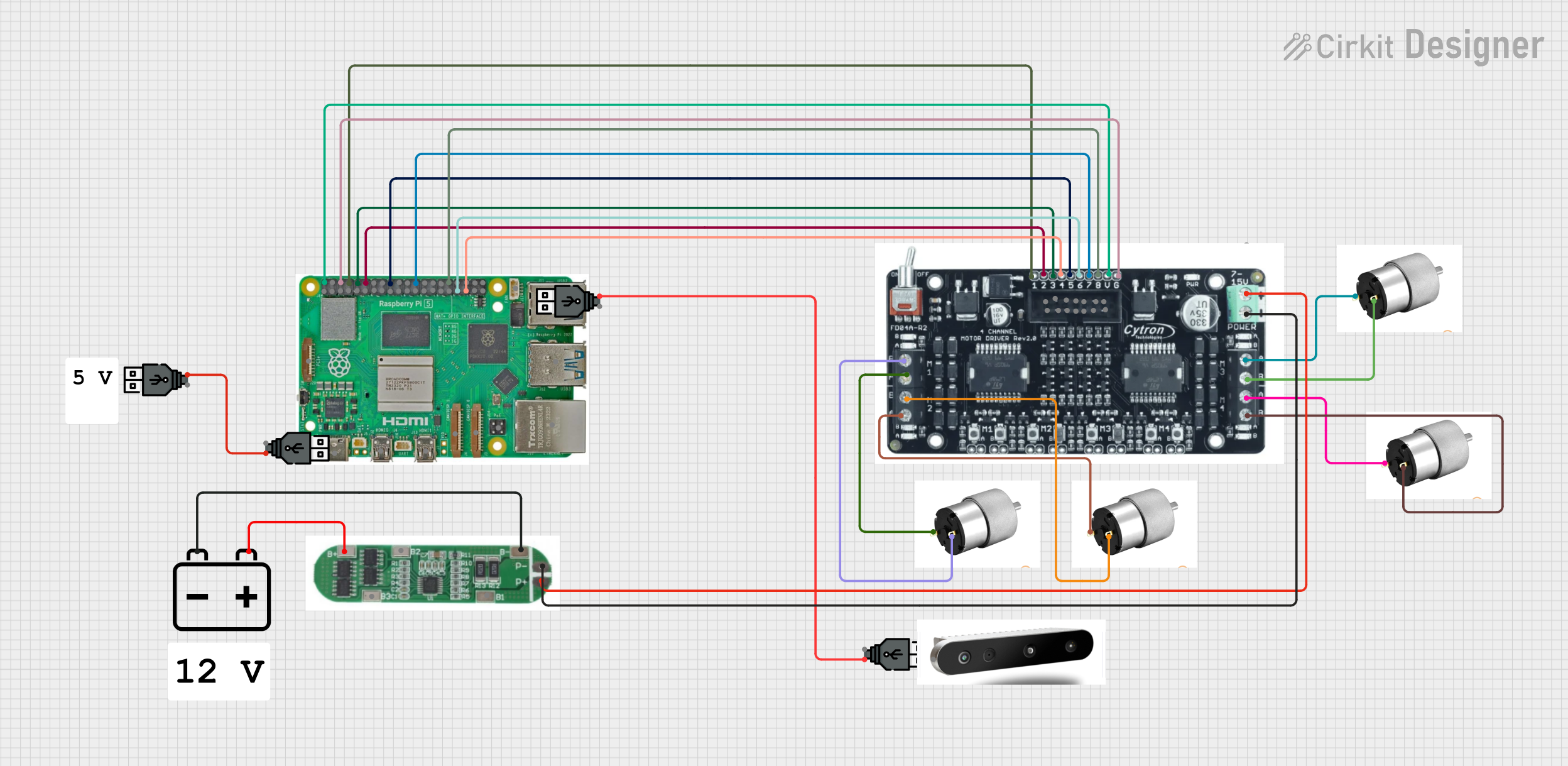
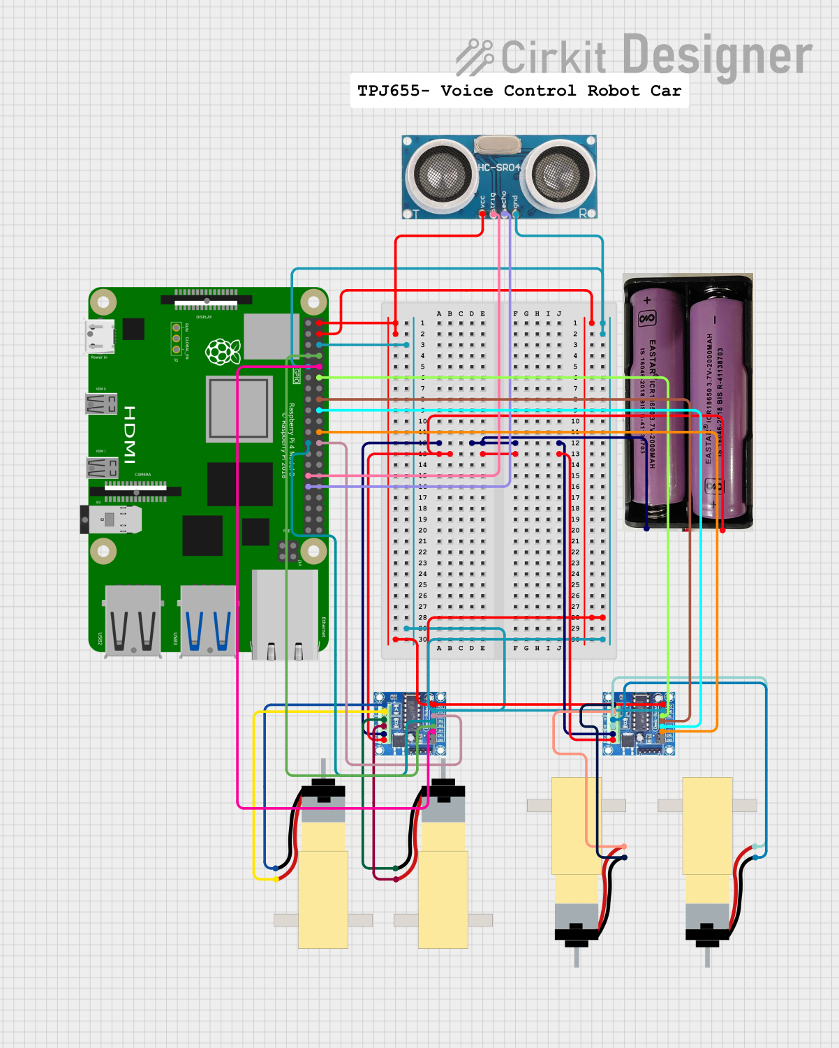
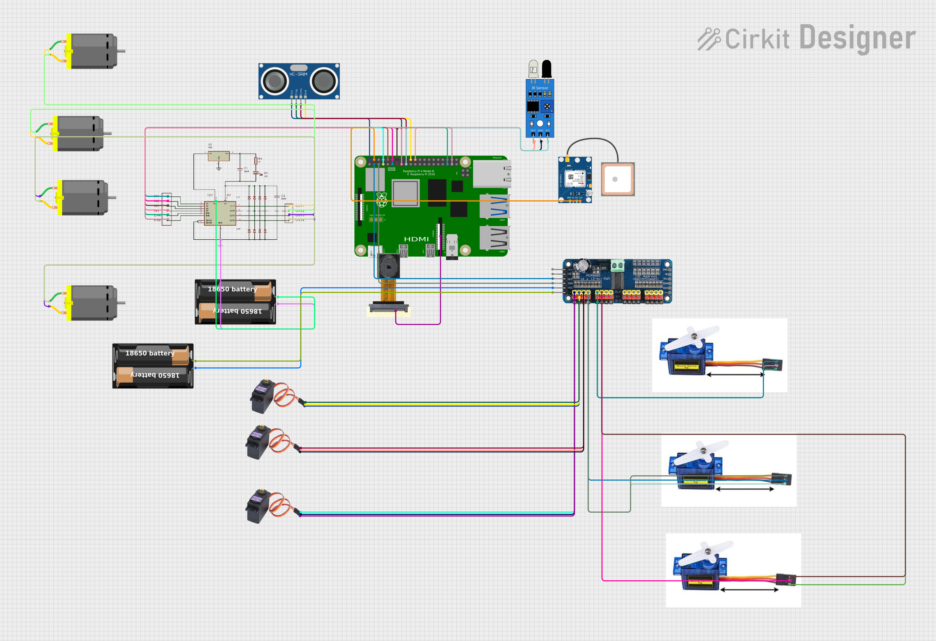
Explore Projects Built with 4 Channel Motor Controller
Common Applications
- Robotics (e.g., controlling robot wheels or arms)
- Conveyor belt systems
- Automated vehicles and drones
- Industrial automation
- DIY electronics projects
Technical Specifications
Below are the key technical details of the 4 Channel Motor Controller:
| Parameter | Value |
|---|---|
| Operating Voltage | 6V to 24V DC |
| Maximum Current (per channel) | 2A continuous, 3A peak |
| Control Signal Voltage | 3.3V or 5V logic compatible |
| PWM Frequency Range | Up to 20 kHz |
| Number of Channels | 4 |
| Motor Types Supported | Brushed DC motors |
| Protection Features | Overcurrent, thermal shutdown, reverse polarity |
Pin Configuration and Descriptions
The 4 Channel Motor Controller typically has the following pin layout:
| Pin Name | Description |
|---|---|
| VCC | Power supply input (6V to 24V DC) |
| GND | Ground connection |
| IN1, IN2 | Control inputs for Motor 1 (direction and speed) |
| IN3, IN4 | Control inputs for Motor 2 (direction and speed) |
| IN5, IN6 | Control inputs for Motor 3 (direction and speed) |
| IN7, IN8 | Control inputs for Motor 4 (direction and speed) |
| OUT1, OUT2 | Motor 1 output terminals |
| OUT3, OUT4 | Motor 2 output terminals |
| OUT5, OUT6 | Motor 3 output terminals |
| OUT7, OUT8 | Motor 4 output terminals |
| ENA, ENB, ENC, END | Enable pins for Motors 1, 2, 3, and 4 respectively |
Usage Instructions
Connecting the Motor Controller
- Power Supply: Connect the VCC pin to a DC power source (6V to 24V) and the GND pin to the ground of the power source.
- Motor Connections: Connect the motor terminals to the corresponding output pins (e.g., OUT1 and OUT2 for Motor 1).
- Control Signals: Connect the control input pins (e.g., IN1, IN2) to a microcontroller or other control device. Use PWM signals to control speed and logic levels to set direction.
- Enable Pins: Ensure the enable pins (ENA, ENB, etc.) are set HIGH to activate the corresponding motor channels.
Example: Using with Arduino UNO
Below is an example of how to control a single motor using the 4 Channel Motor Controller and an Arduino UNO:
// Define motor control pins
const int IN1 = 9;  // Motor 1 direction pin
const int IN2 = 10; // Motor 1 direction pin
const int ENA = 11; // Motor 1 enable pin (PWM for speed control)

void setup() {
  // Set motor control pins as outputs
  pinMode(IN1, OUTPUT);
  pinMode(IN2, OUTPUT);
  pinMode(ENA, OUTPUT);
}

void loop() {
  // Rotate motor in forward direction
  digitalWrite(IN1, HIGH); // Set IN1 HIGH for forward direction
  digitalWrite(IN2, LOW);  // Set IN2 LOW
  analogWrite(ENA, 128);   // Set speed to 50% (PWM value: 128 out of 255)
  delay(2000);             // Run for 2 seconds

  // Stop the motor
  analogWrite(ENA, 0);     // Set speed to 0
  delay(1000);             // Wait for 1 second

  // Rotate motor in reverse direction
  digitalWrite(IN1, LOW);  // Set IN1 LOW for reverse direction
  digitalWrite(IN2, HIGH); // Set IN2 HIGH
  analogWrite(ENA, 200);   // Set speed to ~78% (PWM value: 200 out of 255)
  delay(2000);             // Run for 2 seconds

  // Stop the motor
  analogWrite(ENA, 0);     // Set speed to 0
  delay(1000);             // Wait for 1 second
}
Best Practices
- Use a power supply that matches the voltage and current requirements of your motors.
- Ensure proper heat dissipation for the motor controller, especially when driving high-current motors.
- Use flyback diodes if your motor controller does not have built-in protection to prevent voltage spikes.
- Avoid exceeding the maximum current rating to prevent damage to the controller.
Troubleshooting and FAQs
Common Issues
Motors not running:
- Check if the enable pins (ENA, ENB, etc.) are set HIGH.
- Verify the power supply voltage and connections.
- Ensure the control signals (IN1, IN2, etc.) are correctly configured.
Motor running in the wrong direction:
- Swap the logic levels of the control pins (e.g., IN1 and IN2) to reverse the direction.
Overheating:
- Ensure the motor current does not exceed the controller's maximum rating.
- Add a heatsink or cooling fan if necessary.
PWM not working:
- Verify that the PWM frequency is within the supported range (up to 20 kHz).
- Check the microcontroller's PWM pin configuration.
FAQs
Q: Can I control stepper motors with this controller?
A: No, this controller is designed for brushed DC motors. Stepper motors require a dedicated stepper driver.
Q: Can I use a 12V motor with a 24V power supply?
A: Yes, but you must limit the PWM duty cycle to ensure the motor does not receive more than 12V.
Q: How do I control all four motors simultaneously?
A: Connect each motor to its respective output pins and use separate control signals (IN1-IN8) for each motor. Ensure all enable pins (ENA-END) are set HIGH.
Q: Is this controller compatible with 3.3V logic?
A: Yes, the control inputs are compatible with both 3.3V and 5V logic levels.