How to Use ESP32-S3: Examples, Pinouts, and Specs
Introduction
The ESP32-S3 by Automata (Part ID: ESP32) is a powerful, low-power system on a chip (SoC) designed for Internet of Things (IoT) applications. It integrates both Wi-Fi and Bluetooth capabilities, making it a versatile choice for wireless communication. With its dual-core processor, extensive GPIO pins, and support for a wide range of peripherals, the ESP32-S3 is ideal for smart devices, home automation, wearables, and other applications requiring efficient wireless connectivity.
Explore Projects Built with ESP32-S3


Explore Projects Built with ESP32-S3
Common Applications
- Smart home devices (e.g., smart lights, thermostats)
- Wearable technology
- Industrial IoT systems
- Wireless sensor networks
- Robotics and automation
- Real-time data monitoring and logging
Technical Specifications
The ESP32-S3 is packed with features that make it suitable for a variety of applications. Below are its key technical specifications:
| Parameter | Value |
|---|---|
| Processor | Dual-core Xtensa® LX7, up to 240 MHz |
| Wireless Connectivity | Wi-Fi 802.11 b/g/n (2.4 GHz), Bluetooth 5.0 LE |
| Flash Memory | Up to 16 MB (external flash supported) |
| SRAM | 512 KB internal, with support for external PSRAM |
| GPIO Pins | 45 GPIOs (multiplexed with other functions) |
| Operating Voltage | 3.0V to 3.6V |
| Power Consumption | Ultra-low power modes available (deep sleep current: ~10 µA) |
| Peripherals | SPI, I2C, I2S, UART, ADC, DAC, PWM, CAN, RMT, and more |
| Security Features | AES, SHA, RSA, HMAC, Digital Signature, Secure Boot, Flash Encryption |
| Operating Temperature | -40°C to +85°C |
| Package | QFN48 (7x7 mm) |
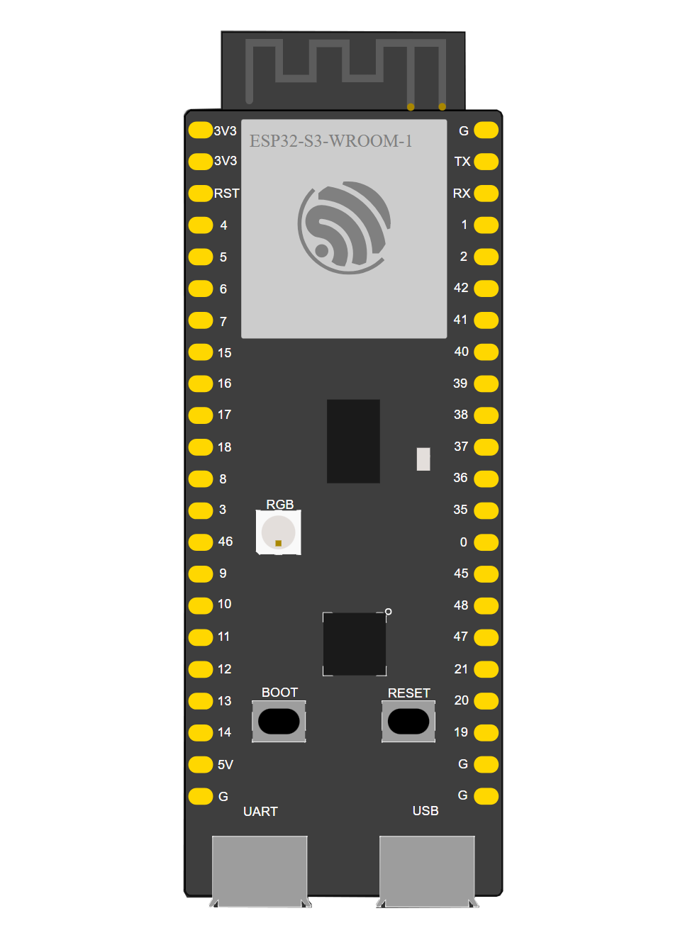
Pin Configuration
The ESP32-S3 has a rich set of GPIO pins and peripherals. Below is a summary of the pin configuration:
| Pin Name | Function | Description |
|---|---|---|
| GPIO0 | Input/Output, Boot Mode | Used for boot mode selection during startup |
| GPIO1-45 | General Purpose I/O | Configurable for digital I/O, ADC, DAC, PWM, etc. |
| EN | Enable | Chip enable pin; active high |
| VDD | Power Supply | 3.3V power input |
| GND | Ground | Ground connection |
| TXD0/RXD0 | UART0 TX/RX | Default UART for serial communication |
| ADC1/ADC2 | Analog Input | 12-bit ADC channels for analog signal measurement |
| SPI Pins | SPI Interface | SPI_CLK, SPI_MOSI, SPI_MISO, SPI_CS for SPI communication |
| I2C Pins | I2C Interface | I2C_SCL, I2C_SDA for I2C communication |
| DAC1/DAC2 | Digital-to-Analog Converter | 8-bit DAC channels for analog signal output |
Note: Some GPIO pins are multiplexed with other functions. Refer to the ESP32-S3 datasheet for detailed pin assignments.
Usage Instructions
The ESP32-S3 is highly versatile and can be used in a variety of circuits. Below are the steps to get started:
Basic Circuit Setup
- Power Supply: Connect the VDD pin to a 3.3V power source and GND to ground.
- Boot Mode: Connect GPIO0 to GND during power-up to enter bootloader mode for programming.
- UART Communication: Use TXD0 and RXD0 for serial communication with a computer or microcontroller.
- Peripherals: Connect peripherals (e.g., sensors, actuators) to the appropriate GPIO pins.
Programming with Arduino IDE
The ESP32-S3 can be programmed using the Arduino IDE. Follow these steps:
- Install the ESP32 Board Support Package in the Arduino IDE.
- Select the correct board (
ESP32-S3) and port from the Tools menu. - Write your code and upload it to the ESP32-S3.
Example Code: Blinking an LED
// This example demonstrates how to blink an LED connected to GPIO2 on the ESP32-S3.

#define LED_PIN 2  // Define the GPIO pin where the LED is connected

void setup() {
  pinMode(LED_PIN, OUTPUT);  // Set the LED pin as an output
}

void loop() {
  digitalWrite(LED_PIN, HIGH);  // Turn the LED on
  delay(1000);                  // Wait for 1 second
  digitalWrite(LED_PIN, LOW);   // Turn the LED off
  delay(1000);                  // Wait for 1 second
}
Important Considerations
- Voltage Levels: Ensure all connected peripherals operate at 3.3V logic levels to avoid damage.
- Power Supply: Use a stable power source to prevent unexpected resets or malfunctions.
- GPIO Usage: Avoid using GPIOs reserved for internal functions (e.g., GPIO6-11 for flash memory).
- Antenna Placement: For optimal wireless performance, ensure the onboard antenna is not obstructed.
Troubleshooting and FAQs
Common Issues
ESP32-S3 Not Detected by Computer
- Ensure the USB cable is functional and supports data transfer.
- Check if the correct COM port is selected in the Arduino IDE.
- Verify that the ESP32-S3 is in bootloader mode (GPIO0 connected to GND during power-up).
Program Upload Fails
- Confirm that the correct board and port are selected in the Arduino IDE.
- Check for loose connections or insufficient power supply.
- Ensure no other application is using the COM port.
Wi-Fi or Bluetooth Not Working
- Verify that the antenna is unobstructed and properly positioned.
- Check the Wi-Fi credentials or Bluetooth pairing settings in your code.
Tips for Troubleshooting
- Use a multimeter to check power supply voltage and continuity of connections.
- Monitor the serial output for error messages or debugging information.
- Update the ESP32 Board Support Package in the Arduino IDE to the latest version.
FAQs
Q: Can the ESP32-S3 operate on battery power?
A: Yes, the ESP32-S3 supports ultra-low power modes, making it suitable for battery-powered applications.
Q: How many devices can the ESP32-S3 connect to via Bluetooth?
A: The ESP32-S3 supports Bluetooth 5.0 LE, allowing multiple simultaneous connections depending on the application.
Q: Can I use the ESP32-S3 with MicroPython?
A: Yes, the ESP32-S3 is compatible with MicroPython. You can flash the MicroPython firmware to the chip and program it using Python.
Q: What is the maximum Wi-Fi range of the ESP32-S3?
A: The Wi-Fi range depends on environmental factors, but it typically covers up to 100 meters in open space.
Q: Is the ESP32-S3 compatible with ESP-IDF?
A: Yes, the ESP32-S3 is fully supported by the ESP-IDF (Espressif IoT Development Framework).
By following this documentation, you can effectively integrate the ESP32-S3 into your projects and troubleshoot common issues.