How to Use CD4511: Examples, Pinouts, and Specs
Introduction
The CD4511, manufactured by Motorola, is a BCD to 7-segment latch/decoder/driver chip. It is designed to convert binary-coded decimal (BCD) inputs into the corresponding 7-segment display outputs. The chip features latching capabilities, which allow it to hold the output state until the next input change. This makes it ideal for driving 7-segment displays in digital systems.
Explore Projects Built with CD4511
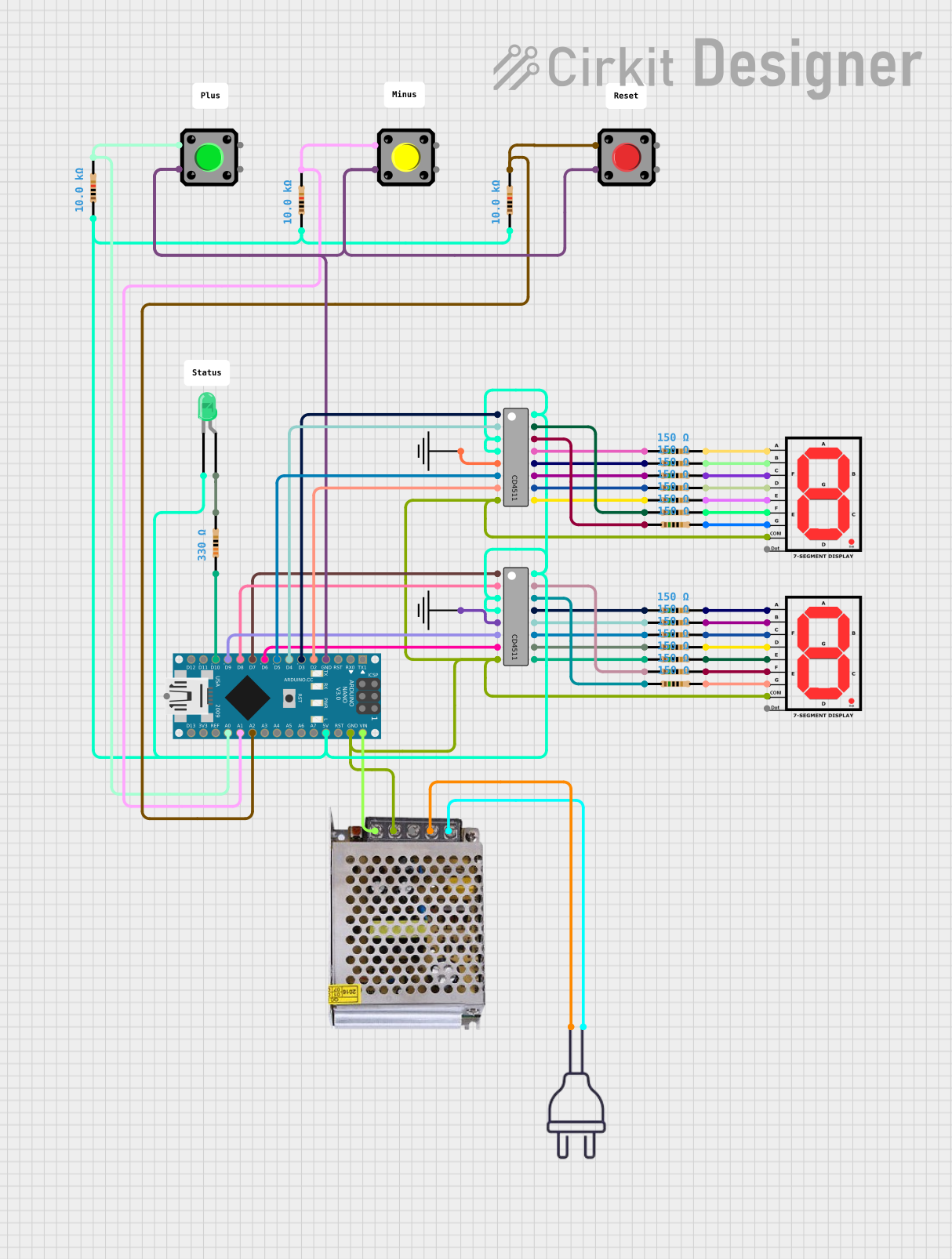

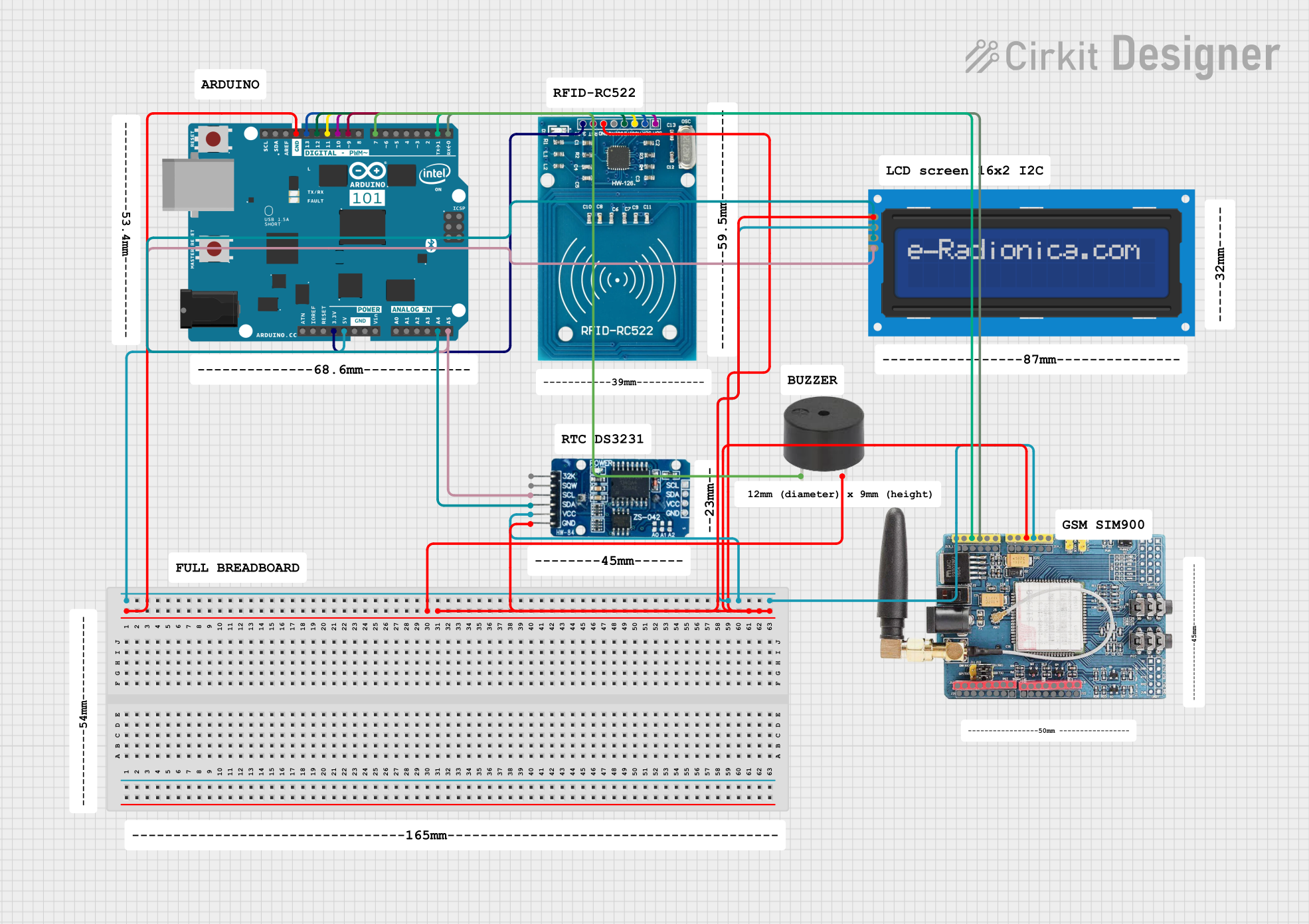

Explore Projects Built with CD4511
Common Applications and Use Cases
- Digital clocks
- Electronic meters
- Counters and timers
- Numeric displays in embedded systems
- Educational projects involving 7-segment displays
Technical Specifications
Below are the key technical details of the CD4511:
| Parameter | Value |
|---|---|
| Supply Voltage (VDD) | 3V to 15V |
| Input Voltage Range | 0V to VDD |
| Maximum Output Current | 25mA per segment |
| Operating Temperature Range | -55°C to +125°C |
| Power Dissipation | 500mW |
| Propagation Delay | 200ns (typical at 5V) |
| Package Types | DIP-16, SOIC-16 |
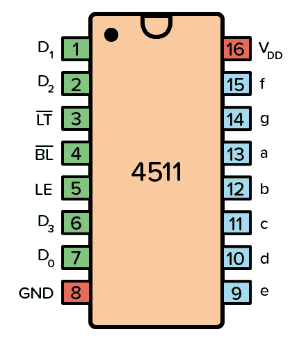
Pin Configuration and Descriptions
The CD4511 comes in a 16-pin package. Below is the pinout and description:
| Pin Number | Pin Name | Description |
|---|---|---|
| 1 | D0 | Least significant bit (LSB) of the BCD input. |
| 2 | D1 | Second bit of the BCD input. |
| 3 | D2 | Third bit of the BCD input. |
| 4 | D3 | Most significant bit (MSB) of the BCD input. |
| 5 | Lamp Test (LT) | Activates all segments for testing when set LOW. |
| 6 | Blanking Input (BI) | Turns off all segments when set LOW, regardless of the BCD input. |
| 7 | Enable Input (LE) | Latches the BCD input when set HIGH. |
| 8 | GND | Ground (0V). |
| 9 | a | Segment "a" output for the 7-segment display. |
| 10 | b | Segment "b" output for the 7-segment display. |
| 11 | c | Segment "c" output for the 7-segment display. |
| 12 | d | Segment "d" output for the 7-segment display. |
| 13 | e | Segment "e" output for the 7-segment display. |
| 14 | f | Segment "f" output for the 7-segment display. |
| 15 | g | Segment "g" output for the 7-segment display. |
| 16 | VDD | Positive supply voltage. |
Usage Instructions
How to Use the CD4511 in a Circuit
- Power Supply: Connect the VDD pin (16) to a positive voltage source (3V to 15V) and the GND pin (8) to ground.
- BCD Input: Provide a 4-bit binary-coded decimal input to pins D0 (1), D1 (2), D2 (3), and D3 (4).
- 7-Segment Display: Connect the segment outputs (pins 9–15) to the corresponding segments of a common-cathode 7-segment display.
- Control Pins:
- Use the Lamp Test (LT) pin (5) to test all segments by setting it LOW.
- Use the Blanking Input (BI) pin (6) to turn off all segments by setting it LOW.
- Use the Latch Enable (LE) pin (7) to latch the current BCD input when set HIGH.
- Current Limiting Resistors: Place resistors (typically 330Ω to 1kΩ) between the segment outputs and the 7-segment display to limit current and protect the display.
Example Circuit with Arduino UNO
Below is an example of how to connect the CD4511 to an Arduino UNO and a 7-segment display:
Circuit Connections
- Connect the Arduino digital pins (e.g., D2–D5) to the CD4511 BCD input pins (D0–D3).
- Connect the CD4511 segment outputs (a–g) to the corresponding segments of the 7-segment display.
- Use a common ground for the Arduino, CD4511, and the 7-segment display.
Arduino Code
// Define BCD input pins connected to the CD4511
const int bcdPins[] = {2, 3, 4, 5}; // D0, D1, D2, D3

void setup() {
  // Set BCD pins as outputs
  for (int i = 0; i < 4; i++) {
    pinMode(bcdPins[i], OUTPUT);
  }
}

void loop() {
  // Display numbers 0 to 9 on the 7-segment display
  for (int number = 0; number < 10; number++) {
    displayNumber(number);
    delay(1000); // Wait 1 second before displaying the next number
  }
}

// Function to display a number on the 7-segment display
void displayNumber(int number) {
  for (int i = 0; i < 4; i++) {
    // Write each bit of the number to the corresponding BCD pin
    digitalWrite(bcdPins[i], (number >> i) & 0x01);
  }
}
Important Considerations and Best Practices
- Ensure the supply voltage (VDD) is within the specified range (3V to 15V).
- Use current-limiting resistors to prevent damage to the 7-segment display.
- Avoid floating inputs by connecting unused input pins to GND or VDD.
- Use the latch feature (LE pin) to stabilize the display output when the BCD input changes rapidly.
Troubleshooting and FAQs
Common Issues and Solutions
No Output on the 7-Segment Display:
- Verify the power supply connections to the CD4511 and the 7-segment display.
- Check the BCD input values and ensure they are within the valid range (0–9).
- Ensure the Blanking Input (BI) pin is not set LOW.
Incorrect Segments Lighting Up:
- Check the wiring between the CD4511 segment outputs and the 7-segment display.
- Verify the BCD input values and ensure they match the desired number.
All Segments Always ON or OFF:
- Ensure the Lamp Test (LT) pin is not permanently set LOW.
- Check the Blanking Input (BI) pin and ensure it is HIGH.
Flickering Display:
- Use the Latch Enable (LE) pin to stabilize the output when the BCD input changes rapidly.
FAQs
Q1: Can the CD4511 drive a common-anode 7-segment display?
No, the CD4511 is designed to drive common-cathode 7-segment displays only.
Q2: What happens if the BCD input is greater than 9?
For BCD inputs greater than 9, the CD4511 outputs undefined states, which may result in random segments lighting up.
Q3: Can I use the CD4511 with a 3.3V microcontroller?
Yes, the CD4511 can operate at 3.3V, but ensure the 7-segment display is compatible with this voltage level.
Q4: Do I need external transistors to drive the 7-segment display?
No, the CD4511 can directly drive the segments of a common-cathode 7-segment display, provided the current does not exceed 25mA per segment.