Cirkit Designer
Your all-in-one circuit design IDE
Home /
Component Documentation
How to Use Stepper Motor (Unipolar): Examples, Pinouts, and Specs
Introduction
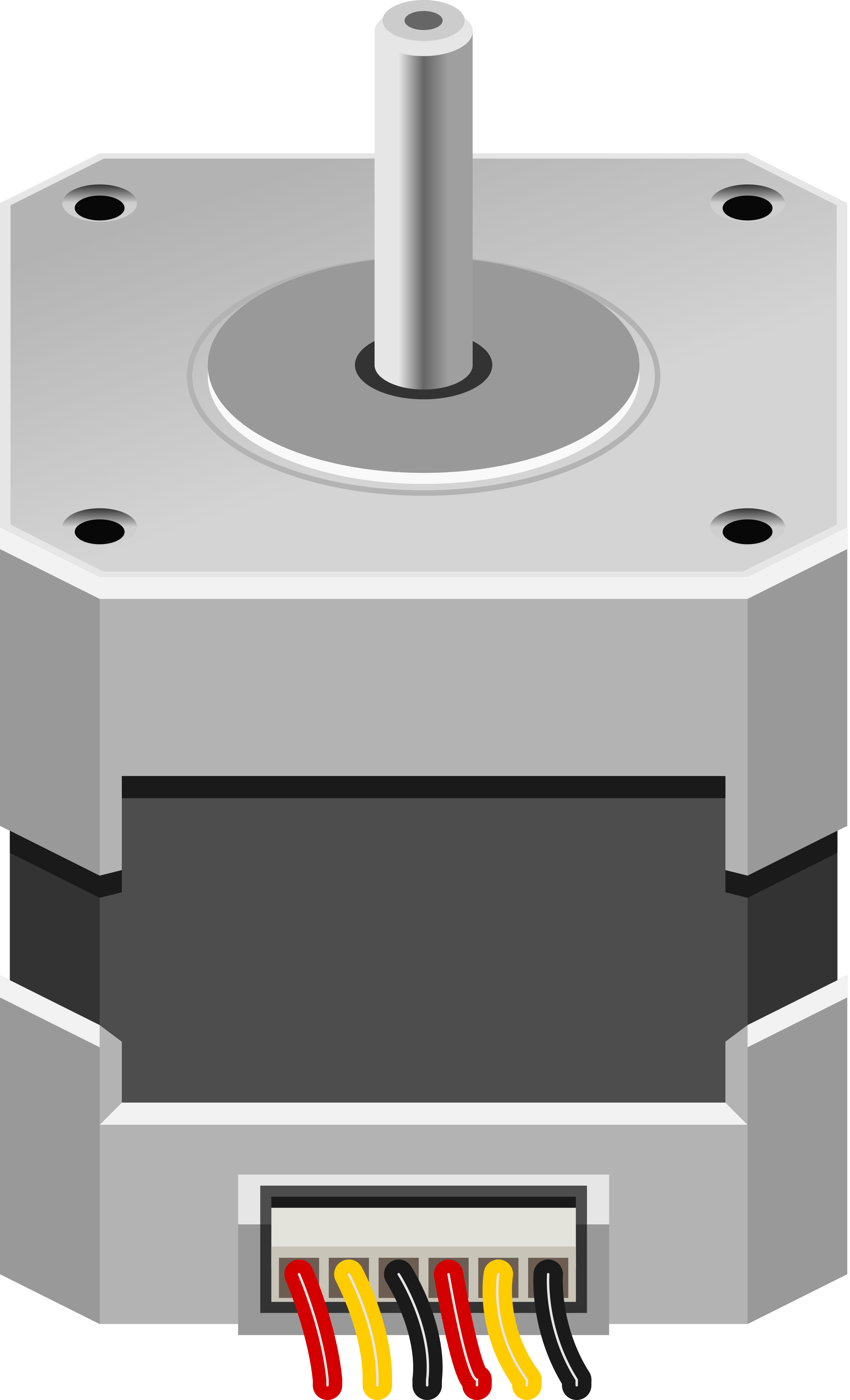
A unipolar stepper motor is a type of electric motor that divides a full rotation into a series of discrete steps. It is called 'unipolar' because of the way the coils are wired, allowing for simpler driving circuitry. Stepper motors are commonly used in precision positioning devices like 3D printers, CNC machines, and robotics due to their ability to accurately control motion.
Explore Projects Built with Stepper Motor (Unipolar)
Arduino-Controlled Bipolar Stepper Motor with MP6500 Driver
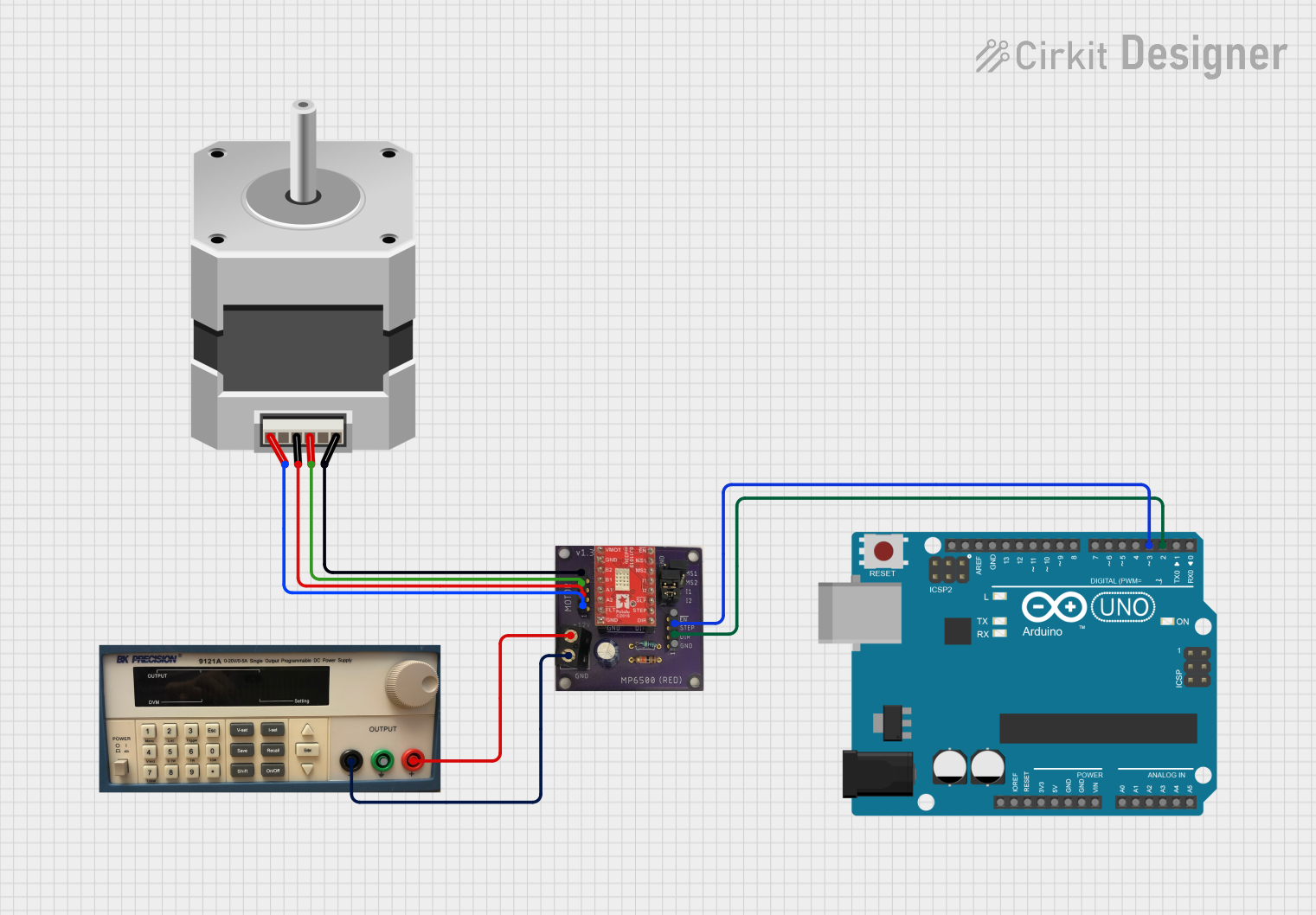
This circuit controls a bipolar stepper motor using an Arduino UNO and an MP6500 stepper motor driver. The Arduino generates step and direction signals to the driver, which in turn powers the motor coils to create precise rotational movements. The motor's rotation direction and step count are programmable, allowing for controlled positioning in applications such as robotics or CNC machines.
Arduino-Controlled Bipolar Stepper Motor with 12V Battery Power
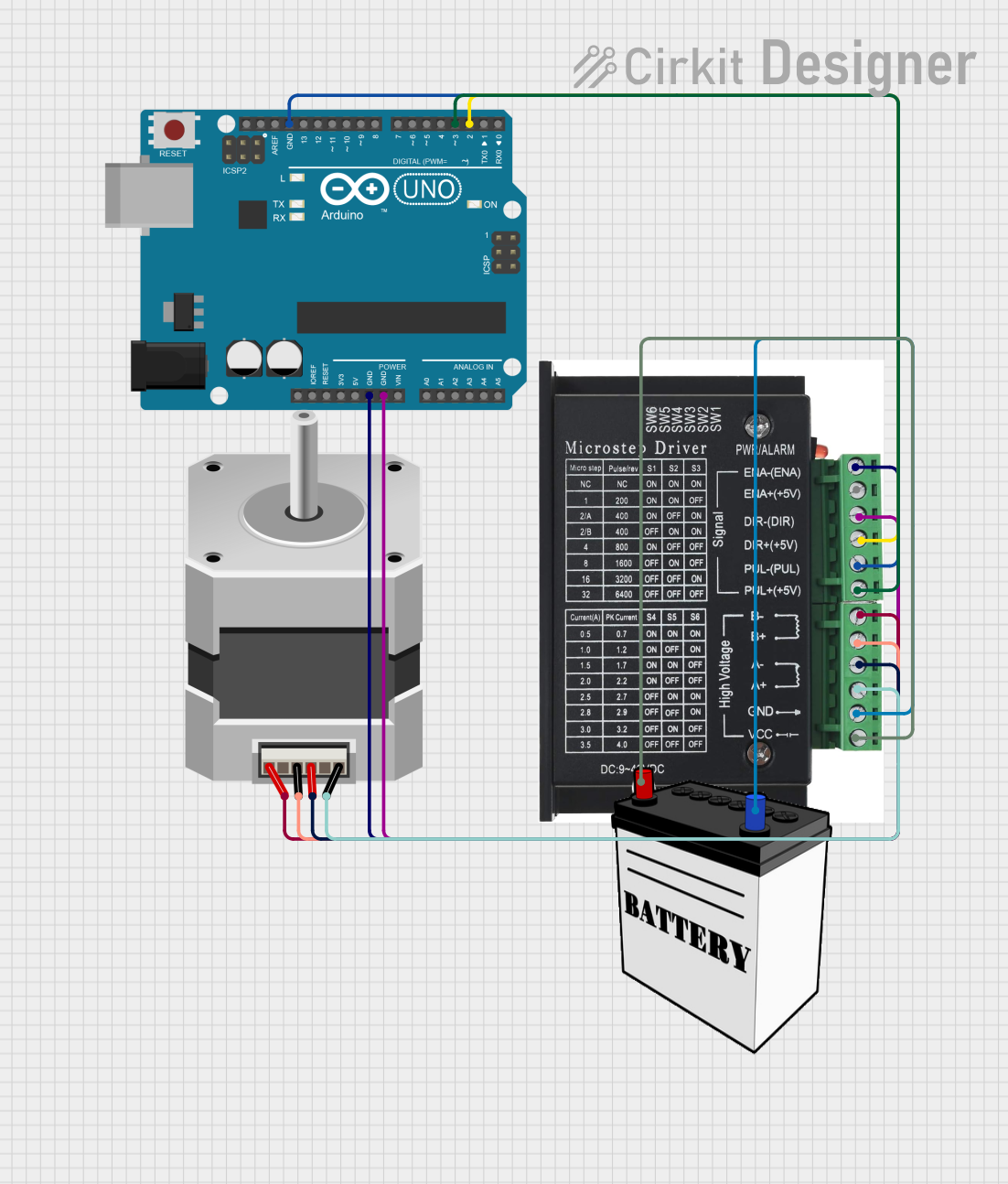
This circuit controls a bipolar stepper motor using an Arduino UNO and a dedicated stepper motor driver. The Arduino generates pulse (step) and direction signals to the driver, which in turn powers the motor coils to rotate the motor in precise increments. The circuit is powered by a 12V battery, and the embedded code on the Arduino allows for the motor to rotate 180 degrees in one direction and then back in the opposite direction.
Arduino-Controlled Bipolar Stepper Motor with A4988 Driver
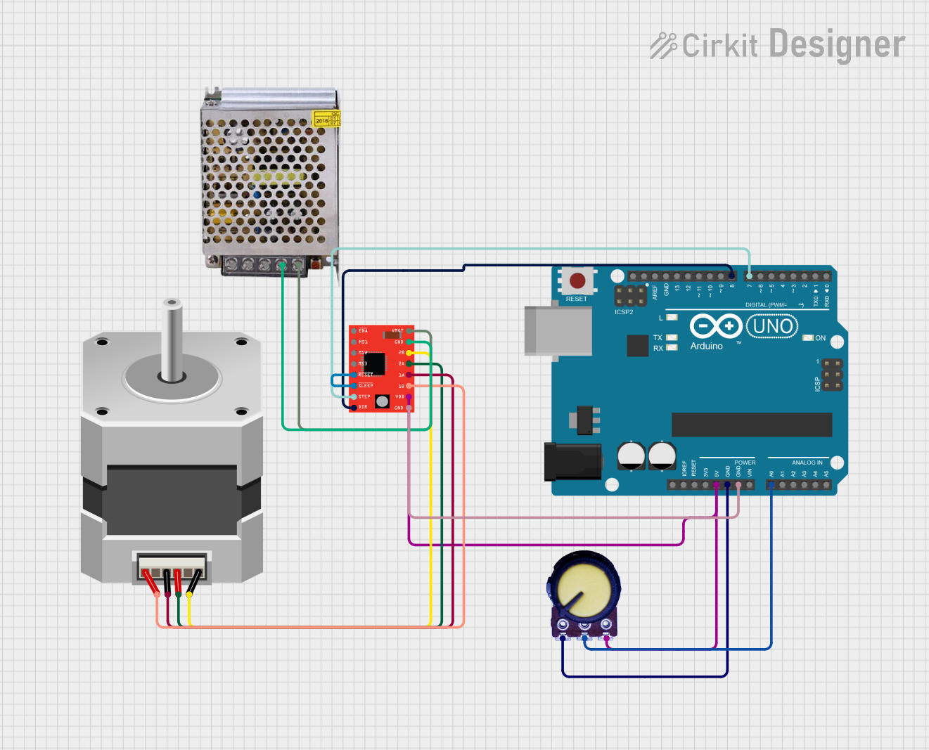
This circuit controls a bipolar stepper motor using an A4988 stepper motor driver, which is interfaced with an Arduino UNO microcontroller. The Arduino provides control signals for the direction (DIR) and stepping (STEP) of the motor, while a potentiometer connected to an analog input (A0) may be used for speed or position feedback. The motor driver is powered by a 12V power supply, and the RESET and SLEEP pins of the driver are connected together, likely to enable the motor driver to operate immediately upon power-up.
Arduino-Controlled Stepper Motor with Potentiometer Feedback

This circuit controls a bipolar stepper motor using an Arduino UNO and an SN754410 quadruple half-H driver. The Arduino adjusts the motor's position based on the input from a rotary potentiometer, allowing for precise control of the stepper motor's steps. The motor's power is supplied through a 2.1mm barrel jack connected to the driver's motor supply pin.
Explore Projects Built with Stepper Motor (Unipolar)
Arduino-Controlled Bipolar Stepper Motor with MP6500 Driver
This circuit controls a bipolar stepper motor using an Arduino UNO and an MP6500 stepper motor driver. The Arduino generates step and direction signals to the driver, which in turn powers the motor coils to create precise rotational movements. The motor's rotation direction and step count are programmable, allowing for controlled positioning in applications such as robotics or CNC machines.
Arduino-Controlled Bipolar Stepper Motor with 12V Battery Power
This circuit controls a bipolar stepper motor using an Arduino UNO and a dedicated stepper motor driver. The Arduino generates pulse (step) and direction signals to the driver, which in turn powers the motor coils to rotate the motor in precise increments. The circuit is powered by a 12V battery, and the embedded code on the Arduino allows for the motor to rotate 180 degrees in one direction and then back in the opposite direction.
Arduino-Controlled Bipolar Stepper Motor with A4988 Driver
This circuit controls a bipolar stepper motor using an A4988 stepper motor driver, which is interfaced with an Arduino UNO microcontroller. The Arduino provides control signals for the direction (DIR) and stepping (STEP) of the motor, while a potentiometer connected to an analog input (A0) may be used for speed or position feedback. The motor driver is powered by a 12V power supply, and the RESET and SLEEP pins of the driver are connected together, likely to enable the motor driver to operate immediately upon power-up.
Arduino-Controlled Stepper Motor with Potentiometer Feedback
This circuit controls a bipolar stepper motor using an Arduino UNO and an SN754410 quadruple half-H driver. The Arduino adjusts the motor's position based on the input from a rotary potentiometer, allowing for precise control of the stepper motor's steps. The motor's power is supplied through a 2.1mm barrel jack connected to the driver's motor supply pin.
Common Applications and Use Cases
- Precision control in robotics
- Positioning in 3D printers
- Movement control in CNC machines
- Automated equipment in manufacturing
Technical Specifications
Key Technical Details
- Step Angle: The angle covered in one step (e.g., 1.8 degrees)
- Voltage Rating: The rated voltage for optimal performance (e.g., 5V)
- Current Rating: The maximum current per phase (e.g., 500mA)
- Resistance: The resistance per phase (e.g., 100 ohms)
- Number of Phases: Typically 4 for unipolar motors
- Holding Torque: The torque when the motor is stationary and powered (e.g., 0.3 Nm)
Pin Configuration and Descriptions
| Pin Number | Description | Color (Typical) |
|---|---|---|
| 1 | Coil 1 Start (A) | Red |
| 2 | Coil 1 End (A') | Yellow |
| 3 | Coil 2 Start (B) | White |
| 4 | Coil 2 End (B') | Blue |
| 5 | Common Wire 1 | Orange |
| 6 | Common Wire 2 | Black |
Usage Instructions
How to Use the Component in a Circuit
- Connect the Coils: Connect the coil start and end pins to the motor driver outputs.
- Power Supply: Ensure the power supply matches the voltage rating of the motor.
- Control Signals: Use a microcontroller to send control signals to the motor driver.
Important Considerations and Best Practices
- Current Limiting: Use a current-limiting driver to prevent damage to the motor.
- Microstepping: For smoother motion, use a driver that supports microstepping.
- Heat Dissipation: Ensure adequate cooling if the motor is operated near its maximum ratings.
Example Code for Arduino UNO
#include <Stepper.h>

// Change these values based on your motor's specifications
const int stepsPerRevolution = 200;  // typically 200 steps for a 1.8 degree step angle
const int motorPin1 = 8;             // Coil 1 Start (A)
const int motorPin2 = 9;             // Coil 1 End (A')
const int motorPin3 = 10;            // Coil 2 Start (B)
const int motorPin4 = 11;            // Coil 2 End (B')

// Initialize the stepper library
Stepper myStepper(stepsPerRevolution, motorPin1, motorPin3, motorPin2, motorPin4);

void setup() {
  // Set the speed in RPMs
  myStepper.setSpeed(60);
}

void loop() {
  // Step one revolution in one direction:
  myStepper.step(stepsPerRevolution);
  delay(500);

  // Step one revolution in the other direction:
  myStepper.step(-stepsPerRevolution);
  delay(500);
}
Troubleshooting and FAQs
Common Issues Users Might Face
- Motor Does Not Rotate: Check wiring and ensure the power supply is correctly rated.
- Motor Vibrates but Does Not Turn: This could be due to incorrect sequencing. Check the control signals.
- Motor Gets Hot: Ensure the current is not exceeding the motor's rating. Improve cooling if necessary.
Solutions and Tips for Troubleshooting
- Check Connections: Verify that all connections are secure and correct.
- Test Power Supply: Use a multimeter to ensure the power supply is delivering the correct voltage.
- Review Code: Ensure the stepping sequence in the code matches the motor's requirements.
FAQs
Q: Can I run a unipolar stepper motor with a bipolar driver?
- A: It is possible by not connecting the common wires, but it's not recommended as it may not utilize the motor efficiently.
Q: How do I know if my stepper motor is unipolar or bipolar?
- A: Unipolar motors typically have 5 or 6 wires, while bipolar motors have 4 wires.
Q: What is the purpose of the common wires in a unipolar stepper motor?
- A: The common wires are used to power the coils and are connected to the positive supply voltage.
Remember to always refer to the specific datasheet of your stepper motor model for precise information and ratings.