How to Use esp32 type c: Examples, Pinouts, and Specs
Introduction
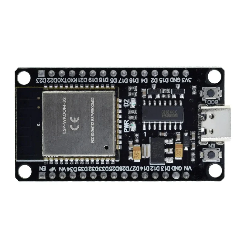
The ESP32 Type-C is a powerful and versatile microcontroller module that integrates Wi-Fi and Bluetooth capabilities. It is based on the ESP32 chip and features a USB Type-C interface for power and programming, making it convenient for modern development environments. The ESP32 Type-C is widely used in IoT applications, home automation, wearable devices, and other projects requiring wireless connectivity and low power consumption.
Common applications include:
- IoT devices and smart home systems
- Wireless sensor networks
- Bluetooth-enabled devices
- Robotics and automation
- Prototyping and development of connected systems
Explore Projects Built with esp32 type c


Explore Projects Built with esp32 type c
Technical Specifications
The ESP32 Type-C offers robust performance and connectivity features. Below are its key technical specifications:
| Parameter | Value |
|---|---|
| Microcontroller | ESP32 dual-core Xtensa LX6 processor |
| Clock Speed | Up to 240 MHz |
| Flash Memory | 4 MB (varies by model) |
| SRAM | 520 KB |
| Wireless Connectivity | Wi-Fi 802.11 b/g/n, Bluetooth 4.2 + BLE |
| USB Interface | USB Type-C for power, programming, and serial communication |
| Operating Voltage | 3.3V |
| Input Voltage Range | 5V (via USB Type-C) |
| GPIO Pins | 30+ (varies by board design) |
| ADC Channels | Up to 18 channels (12-bit resolution) |
| DAC Channels | 2 channels (8-bit resolution) |
| Communication Protocols | UART, SPI, I2C, I2S, CAN, PWM |
| Power Consumption | Ultra-low power consumption in deep sleep mode (~10 µA) |
| Dimensions | Varies by board, typically compact (e.g., 25mm x 50mm) |
Pin Configuration
Below is a typical pinout for the ESP32 Type-C module. Note that the exact pin configuration may vary depending on the specific board manufacturer.
| Pin Name | Function | Description |
|---|---|---|
| VIN | Power Input | Connect to 5V power source via USB Type-C |
| GND | Ground | Common ground for the circuit |
| 3V3 | 3.3V Output | Regulated 3.3V output from onboard regulator |
| EN | Enable | Active-high pin to enable the module |
| GPIO0 | General Purpose I/O | Used for boot mode selection during programming |
| GPIO1-39 | General Purpose I/O | Configurable for digital I/O, ADC, PWM, etc. |
| TXD0 | UART Transmit | Serial communication transmit pin |
| RXD0 | UART Receive | Serial communication receive pin |
| ADC1_CH0-7 | Analog Input | ADC channels for analog-to-digital conversion |
| DAC1, DAC2 | Digital-to-Analog Converter | Output analog signals |
| I2C_SCL | I2C Clock | Clock line for I2C communication |
| I2C_SDA | I2C Data | Data line for I2C communication |
Usage Instructions
How to Use the ESP32 Type-C in a Circuit
- Powering the Module: Connect the ESP32 Type-C to a 5V power source using the USB Type-C port. The onboard voltage regulator will provide the required 3.3V to the ESP32 chip.
- Programming: Use the USB Type-C interface to upload code to the ESP32. It is compatible with the Arduino IDE, PlatformIO, and ESP-IDF.
- Connecting Peripherals: Use the GPIO pins to connect sensors, actuators, and other peripherals. Ensure that the voltage levels are compatible with the ESP32's 3.3V logic.
- Wireless Connectivity: Configure Wi-Fi and Bluetooth settings in your code to enable wireless communication.
Important Considerations and Best Practices
- Voltage Levels: The ESP32 operates at 3.3V logic. Avoid connecting 5V signals directly to its GPIO pins to prevent damage.
- Boot Mode: To enter programming mode, ensure GPIO0 is pulled low during reset.
- Power Supply: Use a stable power source to avoid unexpected resets or instability.
- Heat Management: The ESP32 can get warm during operation. Ensure proper ventilation if used in enclosed spaces.
Example Code for Arduino IDE
Below is an example of how to connect the ESP32 Type-C to a Wi-Fi network and blink an LED:
#include <WiFi.h> // Include the WiFi library

// Replace with your network credentials
const char* ssid = "Your_SSID";
const char* password = "Your_PASSWORD";

const int ledPin = 2; // GPIO2 is typically connected to an onboard LED

void setup() {
  pinMode(ledPin, OUTPUT); // Set the LED pin as an output
  Serial.begin(115200);    // Start serial communication at 115200 baud

  // Connect to Wi-Fi
  Serial.print("Connecting to Wi-Fi");
  WiFi.begin(ssid, password);
  while (WiFi.status() != WL_CONNECTED) {
    delay(500);
    Serial.print(".");
  }
  Serial.println("\nWi-Fi connected!");
  Serial.print("IP Address: ");
  Serial.println(WiFi.localIP());
}

void loop() {
  digitalWrite(ledPin, HIGH); // Turn the LED on
  delay(1000);                // Wait for 1 second
  digitalWrite(ledPin, LOW);  // Turn the LED off
  delay(1000);                // Wait for 1 second
}
Troubleshooting and FAQs
Common Issues
ESP32 Not Detected by Computer:
- Ensure the USB Type-C cable supports data transfer (not just charging).
- Check if the correct drivers for the ESP32 are installed on your computer.
Wi-Fi Connection Fails:
- Verify the SSID and password in your code.
- Ensure the Wi-Fi network is within range and not overloaded.
Module Keeps Resetting:
- Check the power supply for stability. Use a high-quality USB cable and power source.
- Avoid excessive current draw from GPIO pins.
GPIO Pins Not Working:
- Ensure the pins are not being used for other functions (e.g., boot mode).
- Verify the pin configuration in your code.
Tips for Troubleshooting
- Use the Serial Monitor in the Arduino IDE to debug your code and monitor output.
- Refer to the ESP32 datasheet for detailed information on pin functions and electrical characteristics.
- If the module becomes unresponsive, try pressing the reset button or re-flashing the firmware.
By following this documentation, you can effectively utilize the ESP32 Type-C in your projects and troubleshoot common issues with ease.