
How to Use IMU Digital Combo Board 6DOF: Examples, Pinouts, and Specs
 Design with IMU Digital Combo Board 6DOF in Cirkit Designer
Introduction
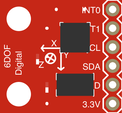
The IMU Digital Combo Board 6DOF (Manufacturer Part ID: SEN-10121) by SparkFun Electronics is a compact and versatile Inertial Measurement Unit (IMU) that integrates an accelerometer and a gyroscope. This combination enables six degrees of freedom (6DOF) motion tracking, making it ideal for applications requiring precise motion sensing and orientation data.
Explore Projects Built with IMU Digital Combo Board 6DOF
 Open Project in Cirkit Designer
 Open Project in Cirkit Designer
 Open Project in Cirkit Designer
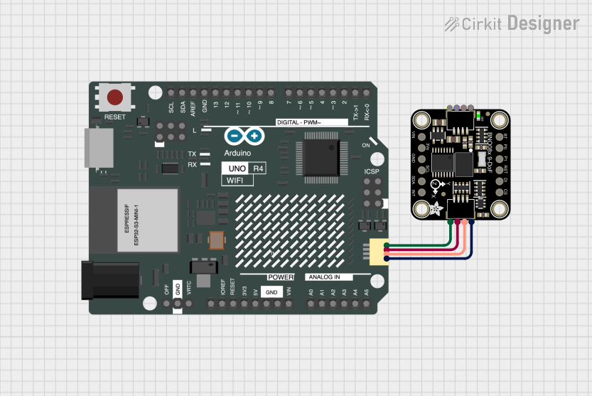 Open Project in Cirkit Designer
Explore Projects Built with IMU Digital Combo Board 6DOF
Open Project in Cirkit DesignerOpen Project in Cirkit DesignerOpen Project in Cirkit DesignerOpen Project in Cirkit DesignerCommon Applications
- Robotics and autonomous systems
- Drone stabilization and navigation
- Motion capture and analysis
- Gaming and virtual reality (VR) controllers
- Wearable devices and fitness trackers
Technical Specifications
The IMU Digital Combo Board 6DOF features the following key specifications:
General Specifications
| Parameter | Value |
|---|---|
| Manufacturer | SparkFun Electronics |
| Part Number | SEN-10121 |
| Degrees of Freedom | 6 (3-axis accelerometer + 3-axis gyroscope) |
| Communication Protocol | I2C |
| Operating Voltage | 3.3V |
| Dimensions | 20.3mm x 20.3mm |
Accelerometer (ADXL345)
| Parameter | Value |
|---|---|
| Measurement Range | ±2g, ±4g, ±8g, ±16g |
| Sensitivity | 256 LSB/g (±2g) |
| Output Data Rate | 0.1 Hz to 3200 Hz |
| Communication Protocol | I2C or SPI |
Gyroscope (ITG-3200)
| Parameter | Value |
|---|---|
| Measurement Range | ±2000°/s |
| Sensitivity | 14.375 LSB/(°/s) |
| Output Data Rate | 1 kHz |
| Communication Protocol | I2C |
Pin Configuration
The IMU Digital Combo Board 6DOF has the following pin layout:
| Pin | Name | Description |
|---|---|---|
| 1 | VCC | Power supply input (3.3V) |
| 2 | GND | Ground |
| 3 | SDA | I2C data line |
| 4 | SCL | I2C clock line |
| 5 | INT1 | Interrupt output from ADXL345 accelerometer |
| 6 | INT2 | Interrupt output from ITG-3200 gyroscope |
Usage Instructions
Connecting the IMU to an Arduino UNO
To use the IMU Digital Combo Board 6DOF with an Arduino UNO, follow these steps:
- Connect the VCC pin of the IMU to the 3.3V pin on the Arduino.
- Connect the GND pin of the IMU to the GND pin on the Arduino.
- Connect the SDA pin of the IMU to the A4 pin on the Arduino (I2C data line).
- Connect the SCL pin of the IMU to the A5 pin on the Arduino (I2C clock line).
Sample Arduino Code
Below is an example Arduino sketch to read data from the IMU using the I2C protocol:
#include <Wire.h>

// I2C addresses for the sensors
#define ACCEL_ADDRESS 0x53  // ADXL345 accelerometer I2C address
#define GYRO_ADDRESS  0x68  // ITG-3200 gyroscope I2C address

void setup() {
  Wire.begin();  // Initialize I2C communication
  Serial.begin(9600);  // Start serial communication for debugging

  // Initialize accelerometer
  Wire.beginTransmission(ACCEL_ADDRESS);
  Wire.write(0x2D);  // Power control register
  Wire.write(0x08);  // Set to measurement mode
  Wire.endTransmission();

  // Initialize gyroscope
  Wire.beginTransmission(GYRO_ADDRESS);
  Wire.write(0x3E);  // Power management register
  Wire.write(0x00);  // Set to normal operation mode
  Wire.endTransmission();
}

void loop() {
  int16_t accelX, accelY, accelZ;
  int16_t gyroX, gyroY, gyroZ;

  // Read accelerometer data
  Wire.beginTransmission(ACCEL_ADDRESS);
  Wire.write(0x32);  // Start reading from data registers
  Wire.endTransmission(false);
  Wire.requestFrom(ACCEL_ADDRESS, 6);  // Request 6 bytes (X, Y, Z)
  if (Wire.available() == 6) {
    accelX = Wire.read() | (Wire.read() << 8);
    accelY = Wire.read() | (Wire.read() << 8);
    accelZ = Wire.read() | (Wire.read() << 8);
  }

  // Read gyroscope data
  Wire.beginTransmission(GYRO_ADDRESS);
  Wire.write(0x1D);  // Start reading from data registers
  Wire.endTransmission(false);
  Wire.requestFrom(GYRO_ADDRESS, 6);  // Request 6 bytes (X, Y, Z)
  if (Wire.available() == 6) {
    gyroX = Wire.read() << 8 | Wire.read();
    gyroY = Wire.read() << 8 | Wire.read();
    gyroZ = Wire.read() << 8 | Wire.read();
  }

  // Print data to Serial Monitor
  Serial.print("Accel: X=");
  Serial.print(accelX);
  Serial.print(" Y=");
  Serial.print(accelY);
  Serial.print(" Z=");
  Serial.println(accelZ);

  Serial.print("Gyro: X=");
  Serial.print(gyroX);
  Serial.print(" Y=");
  Serial.print(gyroY);
  Serial.print(" Z=");
  Serial.println(gyroZ);

  delay(500);  // Delay for readability
}
Best Practices
- Ensure the IMU is powered with a stable 3.3V supply to avoid damage.
- Use pull-up resistors (typically 4.7kΩ) on the SDA and SCL lines if not already present.
- Mount the IMU securely to minimize vibrations and improve measurement accuracy.
- Calibrate the accelerometer and gyroscope for your specific application to improve precision.
Troubleshooting and FAQs
Common Issues
No data or incorrect readings from the IMU.
- Ensure proper wiring and verify connections to the Arduino.
- Check that the IMU is powered with 3.3V (not 5V, which can damage the board).
- Confirm that the I2C addresses (0x53 for ADXL345 and 0x68 for ITG-3200) match the code.
Unstable or noisy sensor readings.
- Use a low-pass filter in software to smooth the data.
- Minimize external vibrations and electromagnetic interference.
Arduino cannot detect the IMU.
- Verify that the SDA and SCL lines are connected to the correct pins.
- Use an I2C scanner sketch to confirm the IMU's presence on the I2C bus.
FAQs
Q: Can I use this IMU with a 5V microcontroller?
A: The IMU operates at 3.3V. If using a 5V microcontroller, use a logic level shifter for the I2C lines to prevent damage.
Q: How do I calibrate the sensors?
A: Calibration involves collecting raw data while the IMU is stationary and calculating offsets for each axis. Apply these offsets in your code to correct the readings.
Q: Can I use SPI instead of I2C?
A: The ADXL345 supports SPI communication, but the ITG-3200 is limited to I2C. For simplicity, use I2C for both sensors.