How to Use Adafruit Thermocouple Amplifier MAX31855: Examples, Pinouts, and Specs
Introduction
The Adafruit Thermocouple Amplifier MAX31855 is a sophisticated breakout board designed for high-precision temperature measurements using K-type thermocouples. This component is ideal for a wide range of applications, including industrial temperature control, HVAC systems, and scientific experiments where accurate temperature readings are crucial. The MAX31855 interfaces with microcontrollers through the Serial Peripheral Interface (SPI) and outputs the temperature in a digital format, making it easy to integrate into various projects.
Explore Projects Built with Adafruit Thermocouple Amplifier MAX31855

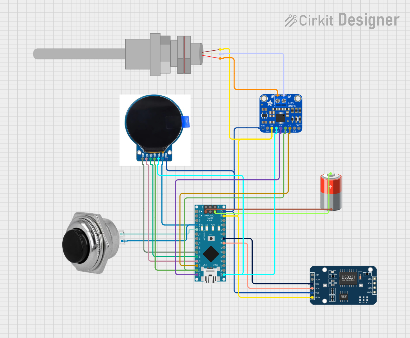
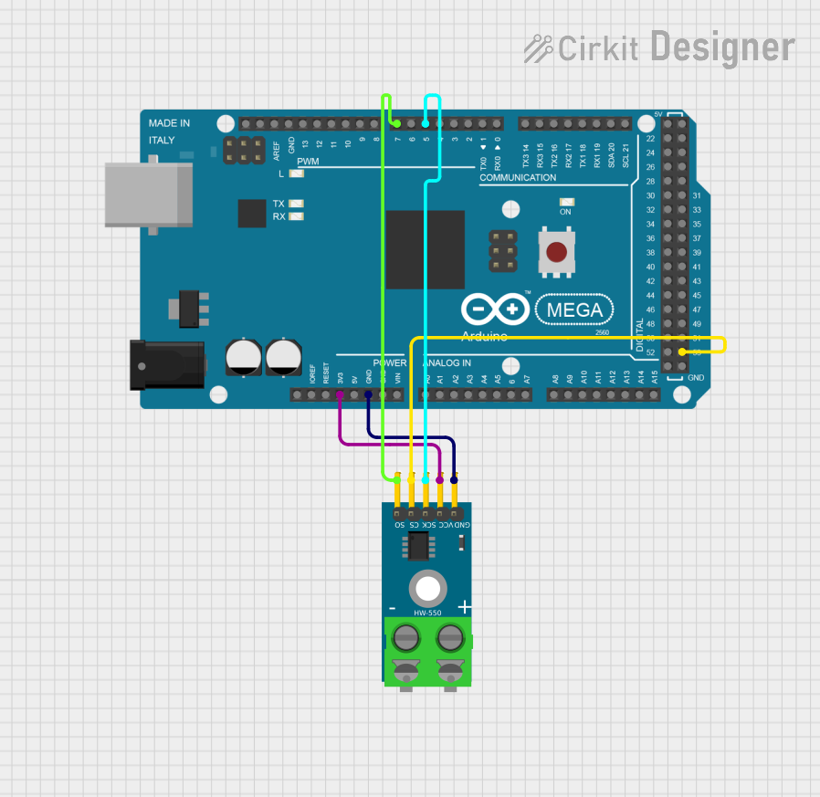
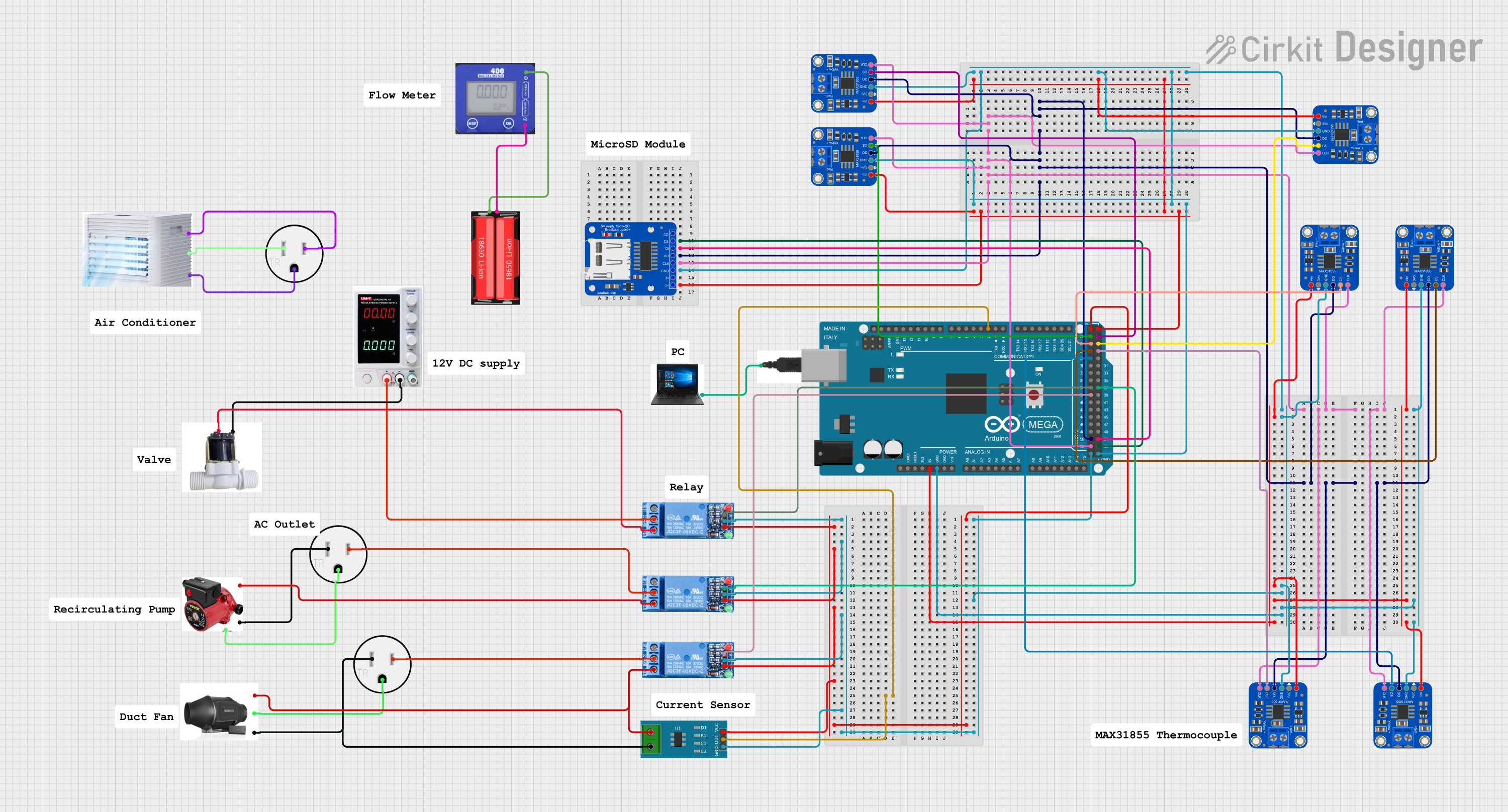
Explore Projects Built with Adafruit Thermocouple Amplifier MAX31855
Technical Specifications
Key Features
- Temperature Range: -200°C to +1350°C (K-type thermocouple)
- Voltage Supply: 3.0V to 3.6V
- Current Consumption: 1.5mA
- Temperature Resolution: 0.25°C
- Interface: SPI
- Output: Digital 14-bit temperature reading (in 0.25°C increments)
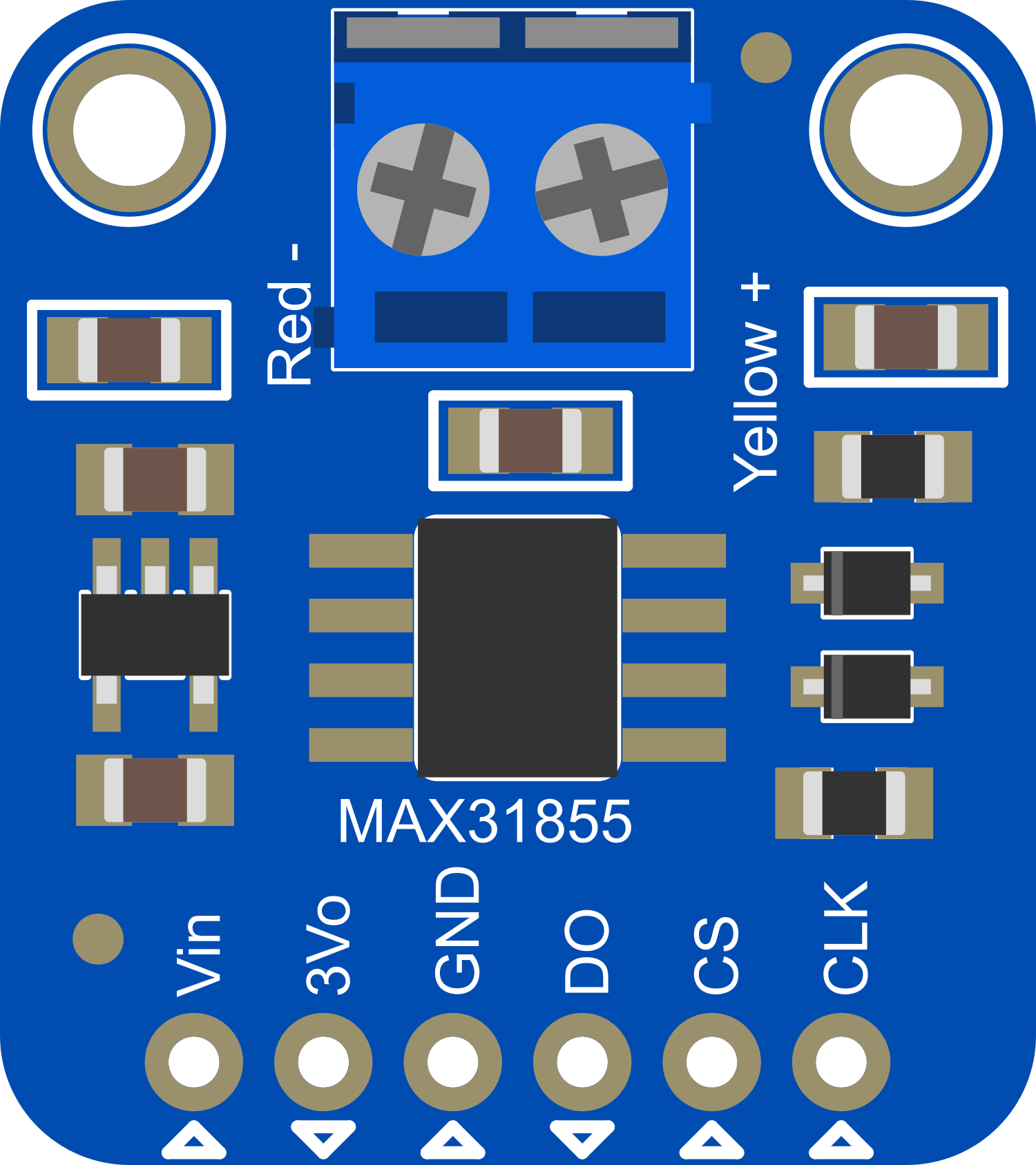
Pin Configuration and Descriptions
| Pin Number | Name | Description |
|---|---|---|
| 1 | VCC | Power supply (3.0V to 3.6V) |
| 2 | GND | Ground connection |
| 3 | DO | Data Output for SPI interface |
| 4 | CS | Chip Select for SPI interface |
| 5 | CLK | Clock Input for SPI interface |
| 6 | NC | No Connection (not used) |
| 7 | NC | No Connection (not used) |
| 8 | NC | No Connection (not used) |
Usage Instructions
Integration with a Circuit
- Power Connections: Connect the VCC pin to a 3.3V supply and the GND pin to the ground.
- SPI Interface: Connect the DO, CS, and CLK pins to the corresponding SPI pins on your microcontroller.
- Thermocouple Connection: Attach the K-type thermocouple leads to the thermocouple input terminals on the breakout board.
Best Practices
- Ensure that the thermocouple is properly connected with the correct polarity.
- Use a stable power supply to avoid fluctuations that could affect the temperature readings.
- Keep the breakout board away from heat sources that could interfere with the measurement.
- Use twisted pair wires for the thermocouple to reduce electrical noise and improve accuracy.
Example Code for Arduino UNO
#include <SPI.h>
#include "Adafruit_MAX31855.h"

// Define the pins used for the SPI connection
int thermoDO = 3;
int thermoCS = 4;
int thermoCLK = 5;

// Initialize the MAX31855 library with the pins
Adafruit_MAX31855 thermocouple(thermoCLK, thermoCS, thermoDO);

void setup() {
  Serial.begin(9600);
  // Check if the thermocouple is connected correctly
  if (!thermocouple.begin()) {
    Serial.println("Thermocouple not connected correctly!");
    while (1) delay(500);
  }
}

void loop() {
  // Read the temperature in Celsius
  double temperature = thermocouple.readCelsius();
  if (isnan(temperature)) {
    Serial.println("Error reading temperature!");
  } else {
    Serial.print("Temperature: ");
    Serial.print(temperature);
    Serial.println(" C");
  }
  delay(1000);
}
Troubleshooting and FAQs
Common Issues
- Incorrect Temperature Readings: Ensure the thermocouple is connected properly and that there are no shorts or open circuits.
- No Data Output: Check the SPI connections and ensure that the correct pins are used for DO, CS, and CLK.
- Fluctuating Readings: Minimize electromagnetic interference by using twisted pair wires for the thermocouple and keeping the breakout board away from noise sources.
FAQs
Q: Can I use a different type of thermocouple with this amplifier? A: No, the MAX31855 is specifically designed for K-type thermocouples.
Q: What should I do if the temperature readings are consistently off by a few degrees? A: You may need to calibrate your system. This can involve comparing the readings from the MAX31855 with a known accurate thermometer and applying an offset in your code if necessary.
Q: How long can the thermocouple wires be? A: Thermocouple wires can be extended, but keep in mind that longer wires can pick up more electrical noise, which can affect accuracy. Use shielded or twisted pair wires for longer distances.
Q: Can the MAX31855 be used with 5V systems? A: The MAX31855 operates at 3.0V to 3.6V. For 5V systems, level shifting or a logic level converter is required for proper communication.
For further assistance, consult the Adafruit MAX31855 datasheet and the Adafruit support forums.