Cirkit Designer Logo
Cirkit Designer
Your all-in-one circuit design IDE
Home / 
Component Documentation

How to Use HC12 SI4463: Examples, Pinouts, and Specs

Image of HC12 SI4463
Cirkit Designer LogoDesign with HC12 SI4463 in Cirkit Designer

Introduction

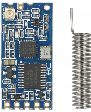
The HC-12 is a versatile, long-range wireless communication module based on the SI4463 RF chip. It operates in the 433 MHz frequency band and supports transparent serial communication, making it ideal for applications requiring wireless data transmission. The module is widely used in IoT projects, remote control systems, telemetry, and wireless sensor networks due to its ease of use and reliable performance.

Common applications include:

  • Wireless data transmission for IoT devices
  • Remote monitoring and control systems
  • Home automation
  • Industrial telemetry
  • Wireless sensor networks

Explore Projects Built with HC12 SI4463

Use Cirkit Designer to design, explore, and prototype these projects online. Some projects support real-time simulation. Click "Open Project" to start designing instantly!
Cellular-Enabled IoT Device with Real-Time Clock and Power Management
Image of LRCM PHASE 2 BASIC: A project utilizing HC12 SI4463 in a practical application
This circuit features a LilyGo-SIM7000G module for cellular communication and GPS functionality, interfaced with an RTC DS3231 for real-time clock capabilities. It includes voltage sensing through two voltage sensor modules, and uses an 8-channel opto-coupler for isolating different parts of the circuit. Power management is handled by a buck converter connected to a DC power source and batteries, with a fuse for protection and a rocker switch for on/off control. Additionally, there's an LED for indication purposes.
Cirkit Designer LogoOpen Project in Cirkit Designer
STM32F103C8T6-Based Water Level Monitoring and Communication System with SIM900A and LoRa Connectivity
Image of water level: A project utilizing HC12 SI4463 in a practical application
This circuit features a microcontroller (STM32F103C8T6) interfaced with a SIM900A GSM module, an HC-SR04 ultrasonic sensor, a water level sensor, and a LoRa Ra-02 SX1278 module for long-range communication. The STM32F103C8T6 is configured to communicate with the GSM module and LoRa module via serial connections, and it reads data from the ultrasonic and water level sensors. An FTDI Programmer is connected for programming and serial communication with the microcontroller.
Cirkit Designer LogoOpen Project in Cirkit Designer
Battery-Powered Emergency Alert System with NUCLEO-F072RB, SIM800L, and GPS NEO 6M
Image of women safety: A project utilizing HC12 SI4463 in a practical application
This circuit is an emergency alert system that uses a NUCLEO-F072RB microcontroller to send SMS alerts and make calls via a SIM800L GSM module, while obtaining location data from a GPS NEO 6M module. The system is powered by a Li-ion battery and includes a TP4056 module for battery charging and protection, with a rocker switch to control power to the microcontroller.
Cirkit Designer LogoOpen Project in Cirkit Designer
STM32H7-Based Multi-Sensor Monitoring System with GSM Alert and LCD Display
Image of medical: A project utilizing HC12 SI4463 in a practical application
This circuit is centered around an STM32H7 microcontroller, which interfaces with a variety of sensors including a DHT11 temperature and humidity sensor, a DS3231 real-time clock, an MQ-2 smoke detector, an IR sensor, a MAX30102 pulse oximeter, and a body temperature sensor. It also includes a GSM module for communication, an LCD display for output, multiple pushbuttons for input, a buzzer, and a speaker for audio signaling. The microcontroller's embedded code suggests that it is programmed to periodically read from the sensors, handle button inputs, update the LCD display, and potentially send alerts via the GSM module.
Cirkit Designer LogoOpen Project in Cirkit Designer

Explore Projects Built with HC12 SI4463

Use Cirkit Designer to design, explore, and prototype these projects online. Some projects support real-time simulation. Click "Open Project" to start designing instantly!
Image of LRCM PHASE 2 BASIC: A project utilizing HC12 SI4463 in a practical application
Cellular-Enabled IoT Device with Real-Time Clock and Power Management
This circuit features a LilyGo-SIM7000G module for cellular communication and GPS functionality, interfaced with an RTC DS3231 for real-time clock capabilities. It includes voltage sensing through two voltage sensor modules, and uses an 8-channel opto-coupler for isolating different parts of the circuit. Power management is handled by a buck converter connected to a DC power source and batteries, with a fuse for protection and a rocker switch for on/off control. Additionally, there's an LED for indication purposes.
Cirkit Designer LogoOpen Project in Cirkit Designer
Image of water level: A project utilizing HC12 SI4463 in a practical application
STM32F103C8T6-Based Water Level Monitoring and Communication System with SIM900A and LoRa Connectivity
This circuit features a microcontroller (STM32F103C8T6) interfaced with a SIM900A GSM module, an HC-SR04 ultrasonic sensor, a water level sensor, and a LoRa Ra-02 SX1278 module for long-range communication. The STM32F103C8T6 is configured to communicate with the GSM module and LoRa module via serial connections, and it reads data from the ultrasonic and water level sensors. An FTDI Programmer is connected for programming and serial communication with the microcontroller.
Cirkit Designer LogoOpen Project in Cirkit Designer
Image of women safety: A project utilizing HC12 SI4463 in a practical application
Battery-Powered Emergency Alert System with NUCLEO-F072RB, SIM800L, and GPS NEO 6M
This circuit is an emergency alert system that uses a NUCLEO-F072RB microcontroller to send SMS alerts and make calls via a SIM800L GSM module, while obtaining location data from a GPS NEO 6M module. The system is powered by a Li-ion battery and includes a TP4056 module for battery charging and protection, with a rocker switch to control power to the microcontroller.
Cirkit Designer LogoOpen Project in Cirkit Designer
Image of medical: A project utilizing HC12 SI4463 in a practical application
STM32H7-Based Multi-Sensor Monitoring System with GSM Alert and LCD Display
This circuit is centered around an STM32H7 microcontroller, which interfaces with a variety of sensors including a DHT11 temperature and humidity sensor, a DS3231 real-time clock, an MQ-2 smoke detector, an IR sensor, a MAX30102 pulse oximeter, and a body temperature sensor. It also includes a GSM module for communication, an LCD display for output, multiple pushbuttons for input, a buzzer, and a speaker for audio signaling. The microcontroller's embedded code suggests that it is programmed to periodically read from the sensors, handle button inputs, update the LCD display, and potentially send alerts via the GSM module.
Cirkit Designer LogoOpen Project in Cirkit Designer

Technical Specifications

The HC-12 module is designed for low-power, long-range communication. Below are its key technical details:

Parameter Specification
Operating Voltage 3.2V to 5.5V
Operating Current 16 mA (transmitting), 3.5 mA (idle)
Frequency Range 433.4 MHz to 473.0 MHz
Communication Range Up to 1,000 meters (open space)
Modulation GFSK
Baud Rate 1,200 to 115,200 bps
Transmit Power Up to 20 dBm (100 mW)
Antenna Interface IPEX or soldered wire antenna
Dimensions 27.8 mm x 14.4 mm x 4 mm

Pin Configuration and Descriptions

The HC-12 module has a total of 4 pins. Below is the pinout and description:

Pin Name Description
1 VCC Power supply input (3.2V to 5.5V). Connect to a regulated power source.
2 GND Ground. Connect to the ground of the circuit.
3 RXD UART Receive pin. Connect to the TX pin of the microcontroller.
4 TXD UART Transmit pin. Connect to the RX pin of the microcontroller.
5 SET Mode selection pin. Pull LOW to enter configuration mode; HIGH for normal mode.

Usage Instructions

How to Use the HC-12 in a Circuit

  1. Power Supply: Connect the VCC pin to a regulated 3.3V or 5V power source and the GND pin to the ground.
  2. UART Communication: Connect the RXD pin of the HC-12 to the TX pin of your microcontroller and the TXD pin to the RX pin of your microcontroller.
  3. Antenna: Attach an appropriate antenna to the module for optimal range and performance.
  4. Mode Selection: Use the SET pin to toggle between normal operation mode (HIGH) and configuration mode (LOW).

Important Considerations and Best Practices

  • Use a decoupling capacitor (e.g., 10 µF) near the VCC and GND pins to ensure stable power supply.
  • Avoid placing the module near high-frequency noise sources to prevent interference.
  • For maximum range, use a high-gain antenna and ensure a clear line of sight between modules.
  • When configuring the module, ensure the SET pin is pulled LOW and use AT commands via UART.

Example: Connecting HC-12 to Arduino UNO

Below is an example of how to connect and use the HC-12 module with an Arduino UNO:

Wiring Diagram

HC-12 Pin Arduino UNO Pin
VCC 5V
GND GND
RXD D3 (via voltage divider if using 5V logic)
TXD D2
SET D4

Arduino Code Example

#include <SoftwareSerial.h>

// Define HC-12 pins for SoftwareSerial
SoftwareSerial HC12(2, 3); // HC-12 TX Pin to Arduino D2, RX Pin to D3

void setup() {
  Serial.begin(9600);       // Start serial communication with PC
  HC12.begin(9600);         // Start serial communication with HC-12
  pinMode(4, OUTPUT);       // Set D4 as output for SET pin
  digitalWrite(4, HIGH);    // Set HC-12 to normal mode
  Serial.println("HC-12 Ready");
}

void loop() {
  // Check if data is received from the PC
  if (Serial.available()) {
    String data = Serial.readString(); // Read data from Serial Monitor
    HC12.println(data);               // Send data to HC-12
  }

  // Check if data is received from HC-12
  if (HC12.available()) {
    String data = HC12.readString();  // Read data from HC-12
    Serial.println(data);             // Send data to Serial Monitor
  }
}

Notes:

  • Ensure the baud rate of the HC-12 matches the one set in the code (default is 9600 bps).
  • Use a voltage divider or logic level shifter if connecting the HC-12 to a 5V microcontroller.

Troubleshooting and FAQs

Common Issues and Solutions

  1. No Communication Between Modules

    • Ensure both modules are configured with the same baud rate and channel.
    • Verify the antenna is properly connected and not damaged.
    • Check wiring connections for loose or incorrect connections.
  2. Short Communication Range

    • Ensure a clear line of sight between modules.
    • Use a higher-gain antenna or increase the transmit power using AT commands.
  3. Module Not Responding to AT Commands

    • Ensure the SET pin is pulled LOW to enter configuration mode.
    • Verify the baud rate of the serial monitor matches the module's configuration.
  4. Interference with Other Devices

    • Change the communication channel using the AT+Cxxx command to avoid conflicts.

FAQs

Q: Can the HC-12 communicate with other 433 MHz devices?
A: No, the HC-12 uses a proprietary protocol and cannot directly communicate with other 433 MHz devices unless they use the same protocol.

Q: How do I reset the HC-12 to factory settings?
A: Pull the SET pin LOW and send the AT+DEFAULT command via UART.

Q: What is the maximum number of HC-12 modules that can communicate simultaneously?
A: Multiple modules can communicate as long as they are on the same channel, but only one module should transmit at a time to avoid collisions.