
How to Use Konektor out5: Examples, Pinouts, and Specs
 Design with Konektor out5 in Cirkit Designer
Introduction
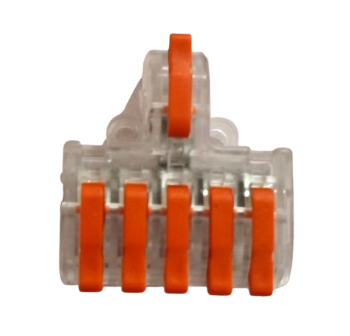
The Konektor out5 is a versatile connector designed for outputting signals or power in electronic circuits. It is engineered for ease of use, allowing quick and reliable connections and disconnections. This component is commonly used in applications where modularity and flexibility are essential, such as prototyping, power distribution, and signal routing in electronic systems.
Explore Projects Built with Konektor out5
 Open Project in Cirkit Designer
 Open Project in Cirkit Designer
 Open Project in Cirkit Designer
 Open Project in Cirkit Designer
Explore Projects Built with Konektor out5
Open Project in Cirkit DesignerOpen Project in Cirkit DesignerOpen Project in Cirkit DesignerOpen Project in Cirkit DesignerCommon Applications:
- Power output connections in electronic devices
- Signal routing in modular systems
- Prototyping and testing circuits
- Interfacing with external peripherals or modules
Technical Specifications
The Konektor out5 is built to handle a wide range of electrical requirements, making it suitable for various applications. Below are its key technical details:
Key Specifications:
| Parameter | Value |
|---|---|
| Maximum Voltage Rating | 30V DC |
| Maximum Current Rating | 5A |
| Connector Type | Male/Female (detachable pair) |
| Contact Material | Gold-plated copper |
| Insulation Material | Polycarbonate (PC) |
| Operating Temperature | -20°C to 85°C |
| Mounting Type | Panel mount or PCB mount |
Pin Configuration and Descriptions:
The Konektor out5 typically consists of two pins for signal or power transmission. Below is the pin configuration:
| Pin Number | Label | Description |
|---|---|---|
| 1 | VOUT | Positive output for signal/power |
| 2 | GND | Ground connection |
Usage Instructions
The Konektor out5 is straightforward to use in electronic circuits. Follow the steps below to integrate it into your project:
Steps to Use:
Mounting the Connector:
- For panel mounting, secure the connector using screws or a locking mechanism.
- For PCB mounting, solder the pins to the designated pads on the PCB.
Wiring:
- Connect the
VOUTpin to the positive output of your circuit. - Connect the
GNDpin to the ground of your circuit.
- Connect the
Connecting and Disconnecting:
- Align the male and female connectors properly before insertion.
- Push the connectors together until they lock securely.
- To disconnect, press the release mechanism (if available) and pull the connectors apart.
Important Considerations:
- Ensure the voltage and current do not exceed the specified ratings (30V DC, 5A).
- Avoid exposing the connector to temperatures beyond its operating range (-20°C to 85°C).
- Use proper insulation to prevent short circuits or accidental disconnections.
Example: Using Konektor out5 with Arduino UNO
The Konektor out5 can be used to output signals or power from an Arduino UNO. Below is an example of connecting an LED to the Konektor out5:
Circuit Setup:
- Connect the
VOUTpin of the Konektor out5 to a digital pin on the Arduino (e.g., pin 9). - Connect the
GNDpin of the Konektor out5 to the Arduino's GND. - Attach an LED and a 220-ohm resistor to the output side of the Konektor out5.
Arduino Code:
// Example code to control an LED via Konektor out5
const int ledPin = 9; // Pin connected to VOUT of Konektor out5

void setup() {
  pinMode(ledPin, OUTPUT); // Set the pin as an output
}

void loop() {
  digitalWrite(ledPin, HIGH); // Turn the LED on
  delay(1000);               // Wait for 1 second
  digitalWrite(ledPin, LOW);  // Turn the LED off
  delay(1000);               // Wait for 1 second
}
Troubleshooting and FAQs
Common Issues:
Loose Connection:
- Cause: Improper alignment or insufficient locking of the connectors.
- Solution: Ensure the connectors are properly aligned and securely locked.
Overheating:
- Cause: Exceeding the maximum current rating (5A).
- Solution: Verify the current draw of your circuit and ensure it is within the specified limit.
Signal Interference:
- Cause: Poor grounding or long cable runs.
- Solution: Use shorter cables and ensure a solid ground connection.
Connector Damage:
- Cause: Exposure to high temperatures or physical stress.
- Solution: Replace the damaged connector and avoid operating outside the specified temperature range.
FAQs:
Q1: Can the Konektor out5 handle AC signals?
A1: Yes, the Konektor out5 can handle AC signals as long as the voltage and current do not exceed the specified ratings.
Q2: Is the Konektor out5 waterproof?
A2: No, the Konektor out5 is not waterproof. Avoid using it in environments with high moisture or water exposure.
Q3: Can I use the Konektor out5 for high-frequency signals?
A3: The Konektor out5 is suitable for low to moderate frequency signals. For high-frequency applications, consider using connectors specifically designed for RF signals.
Q4: How do I clean the connector contacts?
A4: Use a soft, lint-free cloth and isopropyl alcohol to clean the contacts. Avoid abrasive materials that may damage the gold plating.
By following this documentation, you can effectively integrate and troubleshoot the Konektor out5 in your electronic projects.