How to Use Timemer: Examples, Pinouts, and Specs
Introduction
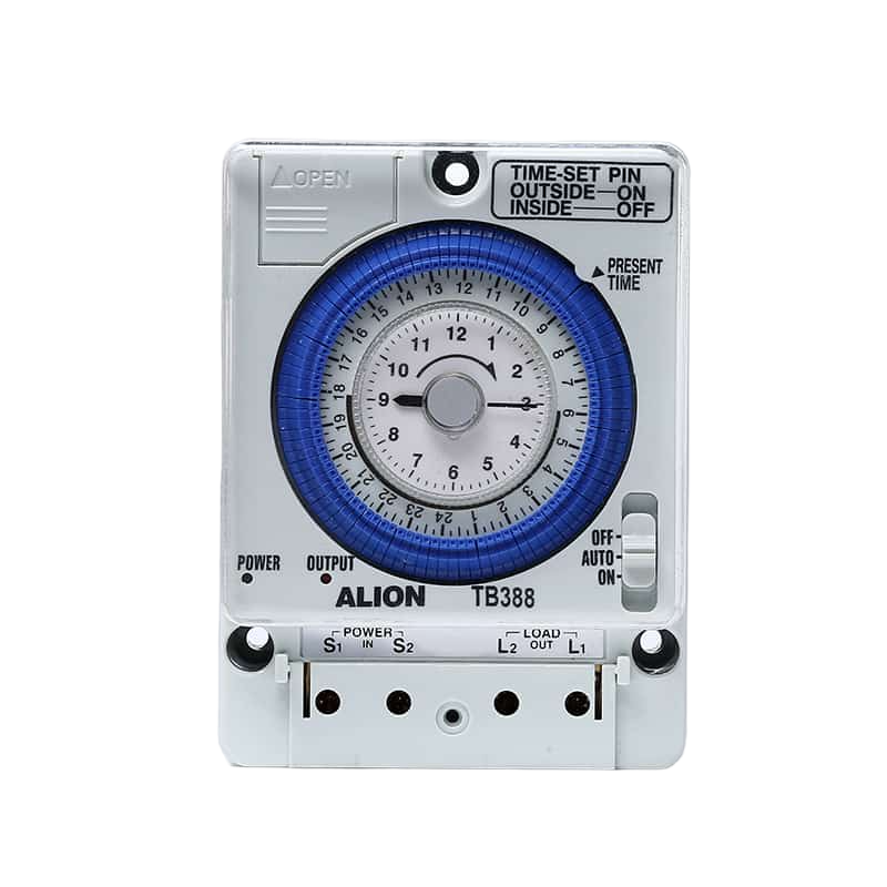
The Timemer is an electronic timing device designed to measure time intervals with high precision. It is commonly used in applications requiring accurate timekeeping, such as in digital clocks, stopwatches, frequency counters, and various timing automation systems. The Timemer can also be integrated into microcontroller projects, such as those involving Arduino UNO, to perform tasks that require precise timing, like pulse width modulation (PWM), event counting, or time-based control of devices.
Explore Projects Built with Timemer
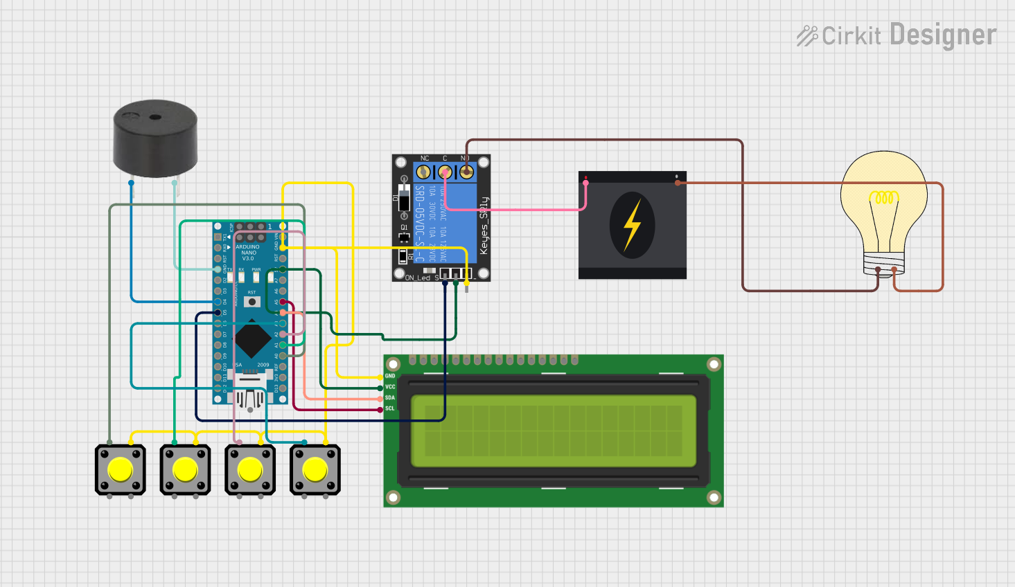
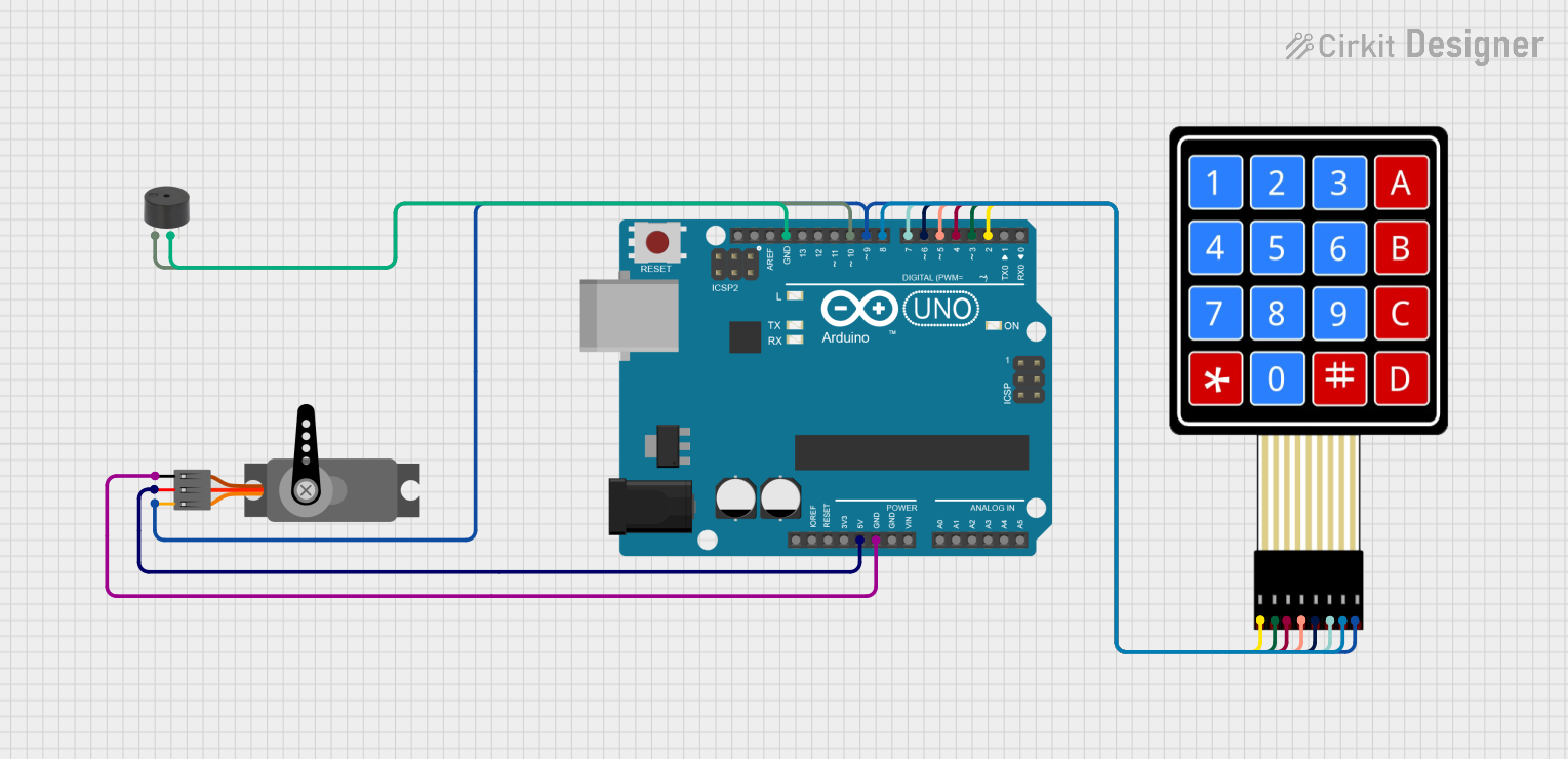
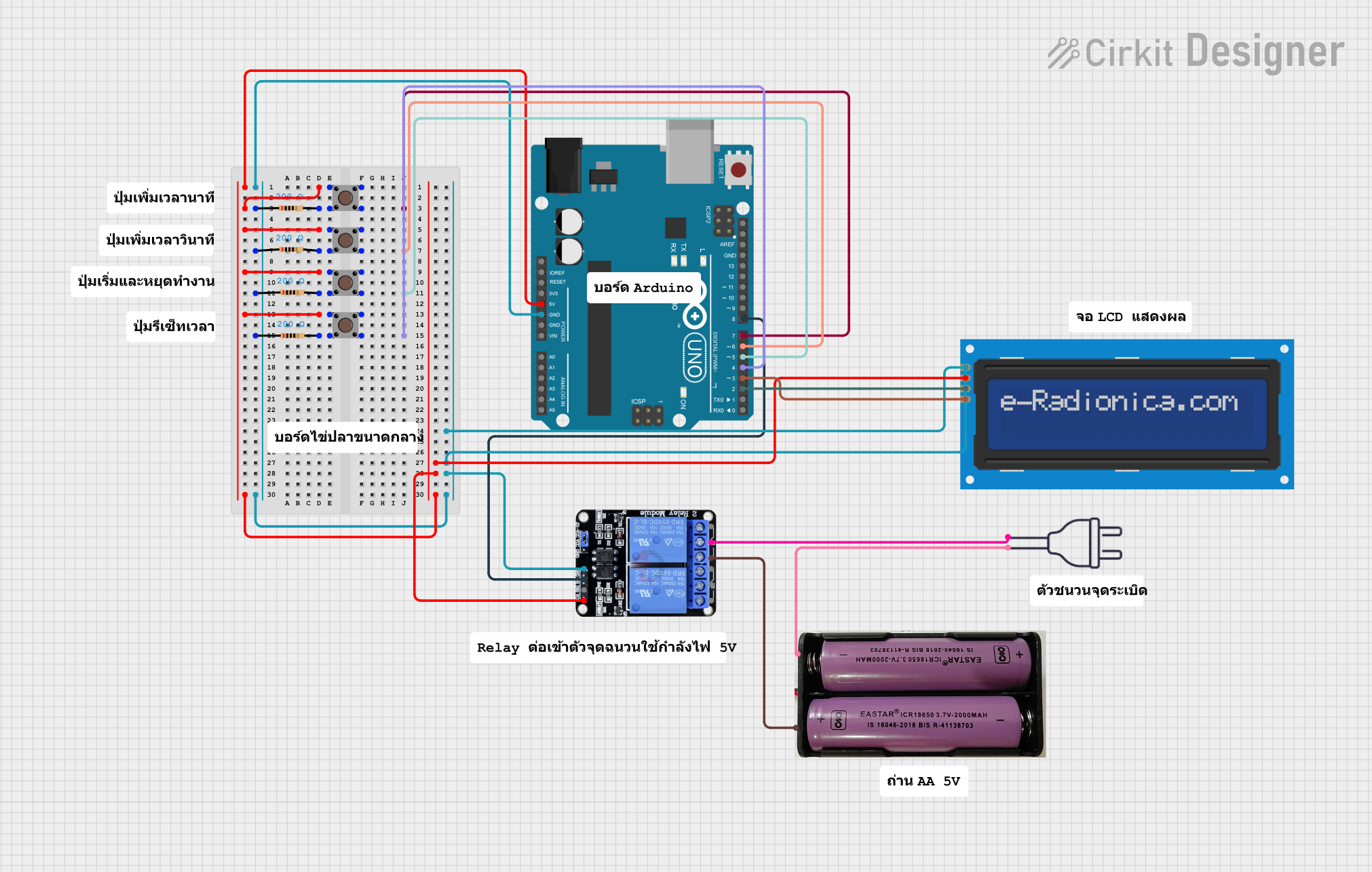
Explore Projects Built with Timemer
Technical Specifications
Key Technical Details
- Timing Accuracy: ±1 ppm (parts per million)
- Operating Voltage: 3.3V to 5V
- Current Consumption: 10 mA (typical)
- Output Frequency Range: 1 Hz to 10 MHz
- Temperature Stability: ±2 ppm/°C
- Interface: Digital pulse output
Pin Configuration and Descriptions
| Pin Number | Name | Description |
|---|---|---|
| 1 | VCC | Power supply (3.3V to 5V) |
| 2 | GND | Ground connection |
| 3 | OUT | Output pulse signal |
| 4 | EN | Enable pin (active high) |
Usage Instructions
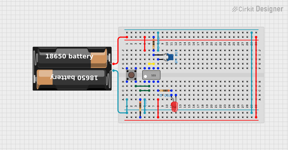
Integrating with a Circuit
- Power Supply: Connect the VCC pin to a 3.3V or 5V power source and the GND pin to the common ground of your circuit.
- Signal Output: Connect the OUT pin to the input of the device that requires timing signals, such as a microcontroller's interrupt or timer/counter pin.
- Enable Pin: The EN pin can be left unconnected for continuous operation or connected to a digital output of a microcontroller to enable/disable the Timemer.
Best Practices
- Use a decoupling capacitor (e.g., 0.1 µF) between VCC and GND close to the Timemer to filter out power supply noise.
- Ensure that the Timemer is placed away from high-temperature sources to maintain timing accuracy.
- Avoid running high-current wires or devices that generate electromagnetic interference near the Timemer.
Example Code for Arduino UNO
// Example code for using the Timemer with an Arduino UNO
const int timemerPin = 2; // Connect the OUT pin of the Timemer to digital pin 2

void setup() {
  pinMode(timemerPin, INPUT);
  attachInterrupt(digitalPinToInterrupt(timemerPin), onTimerEvent, RISING);
  Serial.begin(9600);
}

void loop() {
  // Main loop can be used to perform other tasks
}

// Interrupt service routine called on each pulse from the Timemer
void onTimerEvent() {
  // Increment a counter or perform time-sensitive operations here
  Serial.println("Timer event occurred");
}
Troubleshooting and FAQs
Common Issues
- No Output Signal: Ensure that the VCC and GND connections are secure and within the specified voltage range. Check if the EN pin is active if used.
- Inaccurate Timing: Verify that the Timemer is operating within the recommended temperature range and is not subjected to mechanical vibrations or shocks.
- Intermittent Operation: Check for loose connections and the presence of decoupling capacitors to stabilize the power supply.
FAQs
Q: Can the Timemer be used with a 3.3V system? A: Yes, the Timemer can operate with a power supply ranging from 3.3V to 5V.
Q: How can I adjust the frequency of the output signal? A: The Timemer typically comes with a fixed frequency range. For adjustable frequency, external circuitry or a programmable microcontroller may be required.
Q: Is the Timemer suitable for battery-powered applications? A: With its low current consumption, the Timemer is suitable for battery-powered applications, provided that the power supply voltage is within the specified range.
Remember to always refer to the specific datasheet of the Timemer model you are using for precise specifications and operating conditions.