How to Use OLED: Examples, Pinouts, and Specs
Introduction
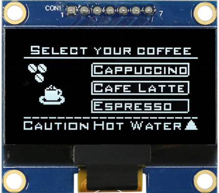
The Midas MDOB128064BV-WS is a high-quality Organic Light Emitting Diode (OLED) display module. OLED technology utilizes organic compounds that emit light when an electric current is applied, eliminating the need for a backlight. This results in displays with exceptional contrast ratios, vibrant colors, and deep blacks. The MDOB128064BV-WS is a 128x64 pixel monochrome display, ideal for applications requiring clear and sharp visuals in a compact form factor.
Explore Projects Built with OLED


Explore Projects Built with OLED
Common Applications
- Wearable devices
- Industrial control panels
- Consumer electronics (e.g., smart home devices)
- Medical equipment
- Prototyping with microcontrollers (e.g., Arduino, Raspberry Pi)
Technical Specifications
The following table outlines the key technical details of the MDOB128064BV-WS OLED display:
| Parameter | Value |
|---|---|
| Display Type | Monochrome OLED |
| Resolution | 128 x 64 pixels |
| Active Area | 26.42mm x 14.70mm |
| Interface | SPI / I2C |
| Operating Voltage | 3.3V - 5V |
| Operating Temperature | -40°C to +80°C |
| Dimensions | 27.3mm x 27.3mm x 1.65mm |
| Manufacturer Part ID | MDOB128064BV-WS |
Pin Configuration
The MDOB128064BV-WS has a standard pinout for SPI/I2C communication. Below is the pin configuration:
SPI Mode Pinout
| Pin | Name | Description |
|---|---|---|
| 1 | GND | Ground (0V reference) |
| 2 | VCC | Power supply (3.3V or 5V) |
| 3 | SCL | Serial Clock Line (SPI Clock) |
| 4 | SDA | Serial Data Line (SPI MOSI) |
| 5 | RES | Reset pin (active low) |
| 6 | DC | Data/Command control pin |
| 7 | CS | Chip Select (active low) |
I2C Mode Pinout
| Pin | Name | Description |
|---|---|---|
| 1 | GND | Ground (0V reference) |
| 2 | VCC | Power supply (3.3V or 5V) |
| 3 | SCL | Serial Clock Line (I2C Clock) |
| 4 | SDA | Serial Data Line (I2C Data) |
| 5 | RES | Reset pin (active low) |
| 6 | DC | Data/Command control pin (optional) |
| 7 | NC | Not connected |
Usage Instructions
Connecting the OLED to an Arduino UNO
The MDOB128064BV-WS can be easily interfaced with an Arduino UNO using either SPI or I2C communication. Below is an example of how to connect the OLED in I2C mode:
Wiring Diagram (I2C Mode)
| OLED Pin | Arduino Pin |
|---|---|
| GND | GND |
| VCC | 5V |
| SCL | A5 (SCL) |
| SDA | A4 (SDA) |
| RES | Digital Pin 8 |
Example Code
The following Arduino sketch demonstrates how to initialize and display text on the OLED using the Adafruit SSD1306 library:
#include <Wire.h>
#include <Adafruit_GFX.h>
#include <Adafruit_SSD1306.h>

// Define OLED display dimensions
#define SCREEN_WIDTH 128
#define SCREEN_HEIGHT 64

// Create an instance of the SSD1306 display object
Adafruit_SSD1306 display(SCREEN_WIDTH, SCREEN_HEIGHT, &Wire, -1);

void setup() {
  // Initialize serial communication for debugging
  Serial.begin(9600);

  // Initialize the OLED display
  if (!display.begin(SSD1306_I2C_ADDRESS, 0x3C)) {
    Serial.println(F("SSD1306 allocation failed"));
    for (;;); // Halt execution if initialization fails
  }

  // Clear the display buffer
  display.clearDisplay();

  // Set text size and color
  display.setTextSize(1); // Small text size
  display.setTextColor(SSD1306_WHITE);

  // Display a message
  display.setCursor(0, 0); // Set cursor to top-left corner
  display.println(F("Hello, OLED!"));
  display.display(); // Render the text on the screen
}

void loop() {
  // Nothing to do here
}
Important Considerations
- Power Supply: Ensure the OLED is powered within its operating voltage range (3.3V to 5V).
- Library Compatibility: Use the Adafruit SSD1306 and GFX libraries for seamless integration.
- Reset Pin: Connect the RES pin to a digital pin on the microcontroller for proper initialization.
- Pull-up Resistors: For I2C communication, ensure pull-up resistors (typically 4.7kΩ) are present on the SCL and SDA lines.
Troubleshooting and FAQs
Common Issues
Display Not Turning On
- Cause: Incorrect wiring or insufficient power supply.
- Solution: Double-check the connections and ensure the power supply is stable.
Garbage Data on Screen
- Cause: Incorrect communication protocol or address.
- Solution: Verify the I2C address (default is 0x3C) and ensure the correct protocol is selected.
Flickering Display
- Cause: Insufficient current supply or loose connections.
- Solution: Use a stable power source and secure all connections.
Library Initialization Fails
- Cause: Missing or outdated libraries.
- Solution: Install the latest Adafruit SSD1306 and GFX libraries via the Arduino Library Manager.
FAQs
Can I use the OLED with a 3.3V microcontroller?
- Yes, the MDOB128064BV-WS is compatible with both 3.3V and 5V logic levels.
What is the default I2C address of the OLED?
- The default I2C address is
0x3C.
- The default I2C address is
Can I use SPI and I2C simultaneously?
- No, the OLED operates in either SPI or I2C mode, but not both at the same time.
How do I change the I2C address?
- The I2C address is fixed and cannot be changed for this module.
By following this documentation, users can effectively integrate the Midas MDOB128064BV-WS OLED display into their projects for high-quality visual output.