How to Use AHT20+BMP280: Examples, Pinouts, and Specs
AHT20 + BMP280 Sensor Module Documentation
1. Introduction
The AHT20 + BMP280 Sensor Module is a versatile and compact environmental sensing solution that combines two powerful sensors in a single module. The AHT20 is a high-precision temperature and humidity sensor, while the BMP280 is a barometric pressure and temperature sensor. Together, they provide accurate measurements of temperature, humidity, and atmospheric pressure, making this module ideal for a wide range of applications.
Common Applications:
- Weather monitoring systems
- IoT (Internet of Things) devices
- Environmental data logging
- HVAC (Heating, Ventilation, and Air Conditioning) systems
- Altitude measurement for drones and other devices
- Smart home automation
2. Technical Specifications
AHT20 Sensor Specifications:
| Parameter | Value |
|---|---|
| Supply Voltage | 2.0V to 5.5V |
| Operating Current | 0.25 mA (average) |
| Temperature Range | -40°C to 85°C |
| Temperature Accuracy | ±0.3°C |
| Humidity Range | 0% to 100% RH |
| Humidity Accuracy | ±2% RH |
| Communication Protocol | I²C |
BMP280 Sensor Specifications:
| Parameter | Value |
|---|---|
| Supply Voltage | 1.71V to 3.6V |
| Operating Current | 2.7 µA (in normal mode) |
| Pressure Range | 300 hPa to 1100 hPa |
| Pressure Accuracy | ±1 hPa |
| Temperature Range | -40°C to 85°C |
| Temperature Accuracy | ±1°C |
| Communication Protocol | I²C or SPI |
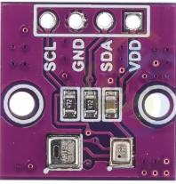
Pin Configuration:
| Pin | Name | Description |
|---|---|---|
| 1 | VCC | Power supply (3.3V or 5V, depending on the module) |
| 2 | GND | Ground |
| 3 | SDA | I²C data line |
| 4 | SCL | I²C clock line |
3. Usage Instructions
Connecting the AHT20 + BMP280 to an Arduino UNO:
Wiring:
- Connect the module's
VCCpin to the Arduino's5Vpin. - Connect the
GNDpin to the Arduino'sGND. - Connect the
SDApin to the Arduino'sA4pin (I²C data line). - Connect the
SCLpin to the Arduino'sA5pin (I²C clock line).
- Connect the module's
Install Required Libraries:
- Install the
Adafruit_AHTX0library for the AHT20 sensor. - Install the
Adafruit_BMP280library for the BMP280 sensor. - These libraries can be installed via the Arduino IDE Library Manager.
- Install the
Arduino Code Example: Below is an example code to read temperature, humidity, and pressure data from the AHT20 and BMP280 sensors.
#include <Wire.h>
#include <Adafruit_AHTX0.h> // Library for AHT20
#include <Adafruit_BMP280.h> // Library for BMP280

// Create sensor objects
Adafruit_AHTX0 aht;
Adafruit_BMP280 bmp;

void setup() {
  Serial.begin(9600);
  while (!Serial); // Wait for Serial Monitor to open

  // Initialize AHT20 sensor
  if (!aht.begin()) {
    Serial.println("Failed to initialize AHT20 sensor!");
    while (1);
  }
  Serial.println("AHT20 sensor initialized.");

  // Initialize BMP280 sensor
  if (!bmp.begin(0x76)) { // Default I²C address for BMP280 is 0x76
    Serial.println("Failed to initialize BMP280 sensor!");
    while (1);
  }
  Serial.println("BMP280 sensor initialized.");
}

void loop() {
  // Read data from AHT20
  sensors_event_t humidity, temp;
  aht.getEvent(&humidity, &temp);

  // Read data from BMP280
  float pressure = bmp.readPressure() / 100.0F; // Convert to hPa
  float altitude = bmp.readAltitude(1013.25); // Sea level pressure in hPa

  // Print sensor data to Serial Monitor
  Serial.print("AHT20 - Temperature: ");
  Serial.print(temp.temperature);
  Serial.print(" °C, Humidity: ");
  Serial.print(humidity.relative_humidity);
  Serial.println(" %");

  Serial.print("BMP280 - Pressure: ");
  Serial.print(pressure);
  Serial.print(" hPa, Altitude: ");
  Serial.print(altitude);
  Serial.println(" m");

  delay(2000); // Wait 2 seconds before next reading
}
Important Considerations:
- Ensure the I²C address of the BMP280 sensor matches the one in the code (default is
0x76). - Use appropriate pull-up resistors (typically 4.7kΩ) on the
SDAandSCLlines if not already included on the module. - Avoid exposing the sensors to extreme conditions (e.g., high humidity or temperature) for prolonged periods to maintain accuracy.
4. Troubleshooting and FAQs
Common Issues and Solutions:
Issue: The sensors are not detected by the Arduino.
- Solution: Check the wiring and ensure the
SDAandSCLlines are connected correctly. Verify the I²C addresses in the code.
- Solution: Check the wiring and ensure the
Issue: Incorrect or fluctuating readings.
- Solution: Ensure the module is not exposed to electrical noise or unstable power supply. Use a decoupling capacitor (e.g., 0.1µF) across the
VCCandGNDpins.
- Solution: Ensure the module is not exposed to electrical noise or unstable power supply. Use a decoupling capacitor (e.g., 0.1µF) across the
Issue: BMP280 altitude readings are inaccurate.
- Solution: Update the sea level pressure value in the code (
1013.25 hPaby default) to match the current atmospheric pressure at your location.
- Solution: Update the sea level pressure value in the code (
FAQs:
Q1: Can I use this module with a 3.3V microcontroller?
A1: Yes, the module supports both 3.3V and 5V logic levels. Ensure the power supply matches your microcontroller's voltage.
Q2: What is the maximum I²C bus speed supported?
A2: The sensors support standard (100 kHz) and fast (400 kHz) I²C speeds.
Q3: Can I use SPI communication for the BMP280?
A3: Yes, the BMP280 supports SPI, but this module is typically configured for I²C communication.
This documentation provides a comprehensive guide to using the AHT20 + BMP280 sensor module. Whether you're a beginner or an experienced user, this guide will help you integrate the module into your projects with ease.
Explore Projects Built with AHT20+BMP280
Explore Projects Built with AHT20+BMP280