
How to Use EB-85A Connector: Examples, Pinouts, and Specs
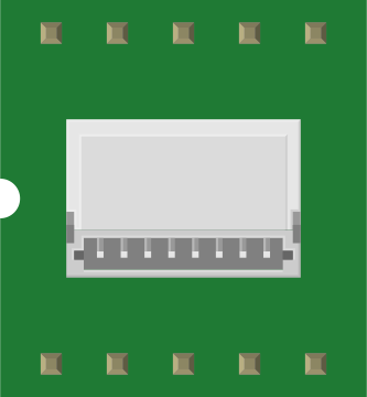
 Design with EB-85A Connector in Cirkit Designer
Introduction
The EB-85A Connector, manufactured by ETek, is a robust electrical connector designed for reliable and secure connections in a wide range of electronic applications. Its durable construction ensures stable performance, making it suitable for both industrial and consumer electronics. The EB-85A is commonly used in power distribution systems, communication devices, and embedded systems where dependable connectivity is critical.
Explore Projects Built with EB-85A Connector
 Open Project in Cirkit Designer
 Open Project in Cirkit Designer
 Open Project in Cirkit Designer
 Open Project in Cirkit Designer
Explore Projects Built with EB-85A Connector
Open Project in Cirkit DesignerOpen Project in Cirkit DesignerOpen Project in Cirkit DesignerOpen Project in Cirkit DesignerCommon Applications
- Power supply connections in industrial equipment
- Signal transmission in communication devices
- Embedded systems and prototyping
- Automotive and aerospace applications
- Consumer electronics requiring secure and stable connections
Technical Specifications
Key Technical Details
| Parameter | Specification |
|---|---|
| Manufacturer | ETek |
| Part ID | EB-85A |
| Connector Type | Electrical Connector |
| Voltage Rating | 250V AC/DC |
| Current Rating | 10A |
| Contact Resistance | ≤ 10 mΩ |
| Insulation Resistance | ≥ 1000 MΩ |
| Operating Temperature | -40°C to +85°C |
| Housing Material | High-strength thermoplastic |
| Contact Material | Gold-plated copper alloy |
| Mounting Style | Panel mount or PCB mount |
| Number of Pins | 4 |
Pin Configuration and Descriptions
| Pin Number | Description | Functionality |
|---|---|---|
| 1 | Power Input (+) | Positive terminal for power input |
| 2 | Power Input (-) | Negative terminal for power input |
| 3 | Signal Line 1 | Data or signal transmission line 1 |
| 4 | Signal Line 2 | Data or signal transmission line 2 |
Usage Instructions
How to Use the EB-85A Connector in a Circuit
- Mounting the Connector:
- For panel mounting, secure the connector using screws or a locking mechanism.
- For PCB mounting, solder the pins to the designated pads on the PCB.
- Wiring:
- Connect the power input terminals (Pin 1 and Pin 2) to the appropriate power source.
- Use signal lines (Pin 3 and Pin 4) for data or communication signals as required by your application.
- Ensure Proper Polarity:
- Double-check the polarity of the power connections to avoid damage to the circuit.
- Testing:
- After installation, test the connections using a multimeter to verify continuity and proper operation.
Important Considerations and Best Practices
- Avoid Overloading: Ensure the current and voltage do not exceed the specified ratings (10A, 250V AC/DC).
- Secure Connections: Use appropriate tools to tighten screws or secure the connector to prevent loose connections.
- Environmental Conditions: Operate the connector within the specified temperature range (-40°C to +85°C) to maintain performance.
- Signal Integrity: For high-speed data transmission, use shielded cables to minimize interference.
Example: Using the EB-85A Connector with an Arduino UNO
The EB-85A Connector can be used to supply power and transmit signals to an Arduino UNO. Below is an example of how to connect the EB-85A to an Arduino UNO for a simple LED control circuit.
Circuit Diagram
- Pin 1 (Power Input +): Connect to the 5V pin on the Arduino.
- Pin 2 (Power Input -): Connect to the GND pin on the Arduino.
- Pin 3 (Signal Line 1): Connect to digital pin 9 on the Arduino (for LED control).
- Pin 4 (Signal Line 2): Not used in this example.
Arduino Code
// Example code to control an LED using the EB-85A Connector
// Pin 3 of the EB-85A is connected to digital pin 9 on the Arduino

const int ledPin = 9; // Define the LED pin connected via EB-85A

void setup() {
  pinMode(ledPin, OUTPUT); // Set the LED pin as an output
}

void loop() {
  digitalWrite(ledPin, HIGH); // Turn the LED on
  delay(1000);               // Wait for 1 second
  digitalWrite(ledPin, LOW);  // Turn the LED off
  delay(1000);               // Wait for 1 second
}
Troubleshooting and FAQs
Common Issues and Solutions
Loose Connections:
- Issue: The connector feels loose or unstable.
- Solution: Ensure the connector is securely mounted and all screws are tightened properly.
No Power or Signal Transmission:
- Issue: The circuit is not receiving power or signals.
- Solution: Check the wiring for proper polarity and continuity using a multimeter.
Overheating:
- Issue: The connector becomes excessively hot during operation.
- Solution: Verify that the current and voltage do not exceed the specified ratings. Reduce the load if necessary.
Signal Interference:
- Issue: Data transmission is unreliable or noisy.
- Solution: Use shielded cables for signal lines and ensure proper grounding.
FAQs
Q1: Can the EB-85A Connector be used outdoors?
A1: The EB-85A is not specifically rated for outdoor use. If used outdoors, ensure it is protected from moisture and extreme environmental conditions.
Q2: What type of cables should I use with the EB-85A?
A2: Use cables with appropriate current and voltage ratings. For signal lines, shielded cables are recommended to minimize interference.
Q3: Can I use the EB-85A Connector for high-frequency signals?
A3: Yes, the EB-85A can handle high-frequency signals, but ensure proper shielding and grounding to maintain signal integrity.
Q4: How do I clean the connector?
A4: Use a soft, dry cloth to clean the connector. Avoid using water or harsh chemicals that may damage the housing or contacts.