Cirkit Designer Logo
Cirkit Designer
Your all-in-one circuit design IDE
Home / 
Component Documentation

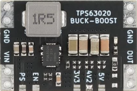
How to Use TPS63020: Examples, Pinouts, and Specs

Image of TPS63020
Cirkit Designer LogoDesign with TPS63020 in Cirkit Designer

Introduction

The TPS63020 is a high-efficiency, step-up/step-down DC-DC converter manufactured by Texas Instruments. It is designed to provide a regulated output voltage from a wide input voltage range, making it ideal for portable and battery-powered applications. The device seamlessly transitions between buck (step-down) and boost (step-up) modes, ensuring efficient operation across varying input conditions.

Explore Projects Built with TPS63020

Use Cirkit Designer to design, explore, and prototype these projects online. Some projects support real-time simulation. Click "Open Project" to start designing instantly!
Solar-Powered Environmental Monitoring System with ESP32 and Cellular Connectivity
Image of IoT Ola: A project utilizing TPS63020 in a practical application
This circuit features an ESP32 microcontroller interfaced with a BME/BMP280 sensor for environmental data and an MH-Z19B sensor for CO2 measurement, both communicating via I2C (SCL, SDA) and serial (TX, RX) connections respectively. It includes a TP4056 module for charging an 18650 Li-ion battery from a solar panel, with a step-up boost converter to provide stable voltage to the MH-Z19B sensor and a voltage regulator for the SIM800L GSM module. The capacitors are likely used for power supply filtering or decoupling.
Cirkit Designer LogoOpen Project in Cirkit Designer
ESP32-Powered Wi-Fi Controlled Robotic Car with OLED Display and Ultrasonic Sensor
Image of playbot: A project utilizing TPS63020 in a practical application
This circuit is a battery-powered system featuring an ESP32 microcontroller that controls an OLED display, a motor driver for two hobby motors, an ultrasonic sensor for distance measurement, and a DFPlayer Mini for audio output through a loudspeaker. The TP4056 module manages battery charging, and a step-up boost converter provides a stable 5V supply to the components.
Cirkit Designer LogoOpen Project in Cirkit Designer
ESP32-Based Environmental Monitoring System with Solar Charging
Image of IoT Ola (Final): A project utilizing TPS63020 in a practical application
This circuit features an ESP32 microcontroller interfaced with a BME/BMP280 sensor for environmental monitoring and an MH-Z19B sensor for CO2 measurement, both communicating via I2C (SCL, SDA) and serial (TX, RX) connections respectively. It includes a SIM800L module for GSM communication, connected to the ESP32 via serial (TXD, RXD). Power management is handled by two TP4056 modules for charging 18650 Li-ion batteries via solar panels, with a step-up boost converter to provide consistent voltage to the MH-Z19B, and voltage regulation for the SIM800L. Decoupling capacitors are used to stabilize the power supply to the BME/BMP280 and ESP32.
Cirkit Designer LogoOpen Project in Cirkit Designer
ESP32 and SIM800L-Based Smart Power Monitor with Voltage Sensors
Image of Generator state monitor: A project utilizing TPS63020 in a practical application
This circuit is a power monitoring and control system that uses an ESP32 microcontroller to read voltage and current values from multiple sensors, calculate power consumption, and send notifications via a SIM800L GSM module. It also includes a TP4056 module for battery charging, a step-up boost converter, and an AC-DC converter to power the system, with the ability to control lights through a relay based on SMS commands.
Cirkit Designer LogoOpen Project in Cirkit Designer

Explore Projects Built with TPS63020

Use Cirkit Designer to design, explore, and prototype these projects online. Some projects support real-time simulation. Click "Open Project" to start designing instantly!
Image of IoT Ola: A project utilizing TPS63020 in a practical application
Solar-Powered Environmental Monitoring System with ESP32 and Cellular Connectivity
This circuit features an ESP32 microcontroller interfaced with a BME/BMP280 sensor for environmental data and an MH-Z19B sensor for CO2 measurement, both communicating via I2C (SCL, SDA) and serial (TX, RX) connections respectively. It includes a TP4056 module for charging an 18650 Li-ion battery from a solar panel, with a step-up boost converter to provide stable voltage to the MH-Z19B sensor and a voltage regulator for the SIM800L GSM module. The capacitors are likely used for power supply filtering or decoupling.
Cirkit Designer LogoOpen Project in Cirkit Designer
Image of playbot: A project utilizing TPS63020 in a practical application
ESP32-Powered Wi-Fi Controlled Robotic Car with OLED Display and Ultrasonic Sensor
This circuit is a battery-powered system featuring an ESP32 microcontroller that controls an OLED display, a motor driver for two hobby motors, an ultrasonic sensor for distance measurement, and a DFPlayer Mini for audio output through a loudspeaker. The TP4056 module manages battery charging, and a step-up boost converter provides a stable 5V supply to the components.
Cirkit Designer LogoOpen Project in Cirkit Designer
Image of IoT Ola (Final): A project utilizing TPS63020 in a practical application
ESP32-Based Environmental Monitoring System with Solar Charging
This circuit features an ESP32 microcontroller interfaced with a BME/BMP280 sensor for environmental monitoring and an MH-Z19B sensor for CO2 measurement, both communicating via I2C (SCL, SDA) and serial (TX, RX) connections respectively. It includes a SIM800L module for GSM communication, connected to the ESP32 via serial (TXD, RXD). Power management is handled by two TP4056 modules for charging 18650 Li-ion batteries via solar panels, with a step-up boost converter to provide consistent voltage to the MH-Z19B, and voltage regulation for the SIM800L. Decoupling capacitors are used to stabilize the power supply to the BME/BMP280 and ESP32.
Cirkit Designer LogoOpen Project in Cirkit Designer
Image of Generator state monitor: A project utilizing TPS63020 in a practical application
ESP32 and SIM800L-Based Smart Power Monitor with Voltage Sensors
This circuit is a power monitoring and control system that uses an ESP32 microcontroller to read voltage and current values from multiple sensors, calculate power consumption, and send notifications via a SIM800L GSM module. It also includes a TP4056 module for battery charging, a step-up boost converter, and an AC-DC converter to power the system, with the ability to control lights through a relay based on SMS commands.
Cirkit Designer LogoOpen Project in Cirkit Designer

Common Applications

  • Smartphones and tablets
  • Wearable devices
  • Portable medical equipment
  • Industrial sensors
  • Battery-powered IoT devices

Technical Specifications

The following table outlines the key technical specifications of the TPS63020:

Parameter Value
Input Voltage Range 1.8 V to 5.5 V
Output Voltage Range 1.2 V to 5.5 V
Output Current Up to 2 A (depending on input/output conditions)
Efficiency Up to 96%
Switching Frequency 2.4 MHz
Operating Temperature Range -40°C to 85°C
Package Type 10-pin VSON (DSJ)

Pin Configuration and Descriptions

The TPS63020 is available in a 10-pin VSON package. The pinout and descriptions are as follows:

Pin Number Pin Name Description
1 L1 Inductor connection 1
2 VIN Input voltage supply
3 EN Enable pin (active high)
4 PGND Power ground
5 FB Feedback pin for output voltage regulation
6 VOUT Regulated output voltage
7 L2 Inductor connection 2
8 AGND Analog ground
9 PS/SYNC Power save mode or synchronization input
10 NC No connection (leave floating or connect to ground)

Usage Instructions

How to Use the TPS63020 in a Circuit

  1. Input and Output Capacitors:

    • Place low-ESR ceramic capacitors (e.g., 10 µF) close to the VIN and VOUT pins to ensure stable operation.
    • Use additional bulk capacitors if the input source is far from the device.
  2. Inductor Selection:

    • Choose an inductor with a saturation current rating higher than the peak current of the TPS63020.
    • A typical value of 1 µH to 2.2 µH is recommended.
  3. Feedback Resistor Network:

    • Use a resistor divider connected to the FB pin to set the desired output voltage.
    • The output voltage can be calculated using the formula:
      [ V_{OUT} = V_{FB} \times \left(1 + \frac{R_1}{R_2}\right) ]
      where ( V_{FB} ) is 0.5 V (internal reference voltage).
  4. Enable Pin:

    • Connect the EN pin to VIN for automatic startup or control it with an external signal.
  5. Power Save Mode:

    • To enable power save mode for light-load efficiency, connect the PS/SYNC pin to ground.
    • For fixed-frequency operation, connect the PS/SYNC pin to VIN or an external clock.

Example Circuit

Below is a basic application circuit for the TPS63020:

VIN ----+----[CIN]----+---- L1 ----+---- L2 ----+----[COUT]---- VOUT
        |             |            |            |
       EN            AGND         PGND         FB
        |             |            |            |
       PS/SYNC       NC           NC           R1
        |                                      |
       GND                                    R2

Arduino UNO Example Code

The TPS63020 can be used to power an Arduino UNO or other microcontrollers. Below is an example of controlling the EN pin using a digital output pin from the Arduino:

// Define the pin connected to the EN pin of TPS63020
const int enablePin = 7;

void setup() {
  // Set the enable pin as an output
  pinMode(enablePin, OUTPUT);

  // Enable the TPS63020 by setting the pin HIGH
  digitalWrite(enablePin, HIGH);

  // Optional: Add a delay to allow the converter to stabilize
  delay(100);
}

void loop() {
  // The TPS63020 remains enabled; add your main code here
}

Important Considerations

  • Ensure proper PCB layout to minimize noise and optimize efficiency. Place input/output capacitors and the inductor as close to the device as possible.
  • Avoid exceeding the maximum input voltage (5.5 V) to prevent damage.
  • Use appropriate thermal management techniques if operating near the maximum current rating.

Troubleshooting and FAQs

Common Issues and Solutions

  1. Output Voltage is Unstable:

    • Verify that the input and output capacitors meet the recommended values.
    • Check the feedback resistor network for proper configuration.
  2. Device Overheating:

    • Ensure the inductor and capacitors are rated for the required current.
    • Improve PCB thermal dissipation by adding copper planes or thermal vias.
  3. No Output Voltage:

    • Confirm that the EN pin is pulled high.
    • Check for proper soldering and connections on all pins.
  4. Low Efficiency at Light Loads:

    • Enable power save mode by grounding the PS/SYNC pin.

FAQs

Q: Can the TPS63020 operate with a single-cell Li-ion battery?
A: Yes, the TPS63020 supports input voltages as low as 1.8 V, making it suitable for single-cell Li-ion batteries.

Q: What happens if the input voltage exceeds the output voltage?
A: The TPS63020 automatically transitions between buck and boost modes to maintain a stable output voltage.

Q: Can I synchronize the TPS63020 with an external clock?
A: Yes, connect the PS/SYNC pin to an external clock signal (up to 2.4 MHz) for synchronization.

Q: Is the TPS63020 suitable for powering sensitive analog circuits?
A: Yes, the device provides a stable and low-noise output, making it suitable for sensitive applications. However, additional filtering may be required for extremely noise-sensitive circuits.