Cirkit Designer Logo
Cirkit Designer
Your all-in-one circuit design IDE
Home / 
Component Documentation

How to Use MIBL 0520: Examples, Pinouts, and Specs

Image of MIBL 0520
Cirkit Designer LogoDesign with MIBL 0520 in Cirkit Designer

Introduction

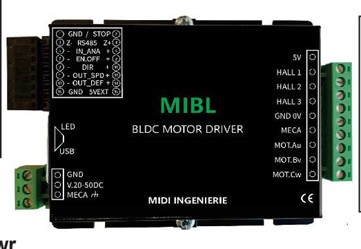
The MIBL 0520 is a high-performance, low-power integrated circuit (IC) designed for a wide range of applications, including signal processing and data conversion. Its compact design makes it an excellent choice for space-constrained environments, such as portable devices, embedded systems, and IoT applications. The MIBL 0520 is engineered to deliver reliable performance while maintaining low power consumption, making it ideal for energy-efficient designs.

Explore Projects Built with MIBL 0520

Use Cirkit Designer to design, explore, and prototype these projects online. Some projects support real-time simulation. Click "Open Project" to start designing instantly!
Arduino Mega 2560 Based Security System with Fingerprint Authentication and SMS Alerts
Image of Door security system: A project utilizing MIBL 0520 in a practical application
This circuit features an Arduino Mega 2560 microcontroller interfaced with a SIM800L GSM module, two fingerprint scanners, an I2C LCD display, an IR sensor, and a piezo buzzer. Power management is handled by a PowerBoost 1000 Basic Pad USB, a TP4056 charging module, and a Li-ion 18650 battery, with an option to use a Mini AC-DC 110V-230V to 5V 700mA module for direct power supply. The primary functionality appears to be a security system with GSM communication capabilities, biometric access control, and visual/audible feedback.
Cirkit Designer LogoOpen Project in Cirkit Designer
MakerEdu Creator with Bluetooth, IR Sensors, LCD Display, and Push Button Interaction
Image of MKL Distance Measurement: A project utilizing MIBL 0520 in a practical application
This circuit features a MakerEdu Creator microcontroller board interfaced with two MKE-S11 IR Infrared Obstacle Avoidance Sensors, a MKE-M02 Push Button Tact Switch, a MKE-M15 Bluetooth module, and a MKE-M08 LCD2004 I2C display module. The push button is connected to a digital input for user interaction, while the IR sensors are likely used for detecting obstacles. The Bluetooth module enables wireless communication, and the LCD display provides a user interface for displaying information or statuses.
Cirkit Designer LogoOpen Project in Cirkit Designer
Arduino UNO RFID Access Control System with LCD Feedback and Servo Operation
Image of door lock: A project utilizing MIBL 0520 in a practical application
This circuit features an Arduino UNO as the central microcontroller, interfaced with an RFID-RC522 module for RFID reading capabilities, and a 16x2 LCD screen with I2C for display. It also includes a 4x4 membrane matrix keypad for user input, a buzzer for audio feedback, and two Tower Pro SG90 servos for actuation. The MB102 Breadboard Power Supply Module provides power to the servos, while the Arduino powers the other components.
Cirkit Designer LogoOpen Project in Cirkit Designer
Mega2560-Controlled Automation System with Non-Contact Liquid Level Sensing and Motor Control
Image of Project_AutomaticBartender: A project utilizing MIBL 0520 in a practical application
This circuit appears to be a complex control system centered around an Arduino Mega2560 R3 Pro microcontroller, which interfaces with multiple sensors (XKC-Y26-V non-contact liquid level sensors and an LM35 temperature sensor), servo motors, a touch display, and an IBT-2 H-Bridge motor driver for controlling a planetary gearbox motor. The system also includes a UART TTL to RS485 converter for communication, likely with the touch display, and a power management subsystem with a switching power supply, fuses, and circuit breakers for safety and voltage regulation (XL4016). The absence of embedded code suggests that the functionality of the microcontroller is not defined within the provided data.
Cirkit Designer LogoOpen Project in Cirkit Designer

Explore Projects Built with MIBL 0520

Use Cirkit Designer to design, explore, and prototype these projects online. Some projects support real-time simulation. Click "Open Project" to start designing instantly!
Image of Door security system: A project utilizing MIBL 0520 in a practical application
Arduino Mega 2560 Based Security System with Fingerprint Authentication and SMS Alerts
This circuit features an Arduino Mega 2560 microcontroller interfaced with a SIM800L GSM module, two fingerprint scanners, an I2C LCD display, an IR sensor, and a piezo buzzer. Power management is handled by a PowerBoost 1000 Basic Pad USB, a TP4056 charging module, and a Li-ion 18650 battery, with an option to use a Mini AC-DC 110V-230V to 5V 700mA module for direct power supply. The primary functionality appears to be a security system with GSM communication capabilities, biometric access control, and visual/audible feedback.
Cirkit Designer LogoOpen Project in Cirkit Designer
Image of MKL Distance Measurement: A project utilizing MIBL 0520 in a practical application
MakerEdu Creator with Bluetooth, IR Sensors, LCD Display, and Push Button Interaction
This circuit features a MakerEdu Creator microcontroller board interfaced with two MKE-S11 IR Infrared Obstacle Avoidance Sensors, a MKE-M02 Push Button Tact Switch, a MKE-M15 Bluetooth module, and a MKE-M08 LCD2004 I2C display module. The push button is connected to a digital input for user interaction, while the IR sensors are likely used for detecting obstacles. The Bluetooth module enables wireless communication, and the LCD display provides a user interface for displaying information or statuses.
Cirkit Designer LogoOpen Project in Cirkit Designer
Image of door lock: A project utilizing MIBL 0520 in a practical application
Arduino UNO RFID Access Control System with LCD Feedback and Servo Operation
This circuit features an Arduino UNO as the central microcontroller, interfaced with an RFID-RC522 module for RFID reading capabilities, and a 16x2 LCD screen with I2C for display. It also includes a 4x4 membrane matrix keypad for user input, a buzzer for audio feedback, and two Tower Pro SG90 servos for actuation. The MB102 Breadboard Power Supply Module provides power to the servos, while the Arduino powers the other components.
Cirkit Designer LogoOpen Project in Cirkit Designer
Image of Project_AutomaticBartender: A project utilizing MIBL 0520 in a practical application
Mega2560-Controlled Automation System with Non-Contact Liquid Level Sensing and Motor Control
This circuit appears to be a complex control system centered around an Arduino Mega2560 R3 Pro microcontroller, which interfaces with multiple sensors (XKC-Y26-V non-contact liquid level sensors and an LM35 temperature sensor), servo motors, a touch display, and an IBT-2 H-Bridge motor driver for controlling a planetary gearbox motor. The system also includes a UART TTL to RS485 converter for communication, likely with the touch display, and a power management subsystem with a switching power supply, fuses, and circuit breakers for safety and voltage regulation (XL4016). The absence of embedded code suggests that the functionality of the microcontroller is not defined within the provided data.
Cirkit Designer LogoOpen Project in Cirkit Designer

Common Applications and Use Cases

  • Signal processing in audio and communication systems
  • Data conversion in analog-to-digital or digital-to-analog systems
  • Portable and battery-powered devices
  • IoT devices requiring compact and efficient ICs
  • Embedded systems with space and power constraints

Technical Specifications

Key Technical Details

Parameter Value
Supply Voltage (Vcc) 2.7V to 5.5V
Operating Current 1.2 mA (typical)
Power Consumption Low power, < 10 mW
Operating Temperature -40°C to +85°C
Package Type 8-pin SOIC (Small Outline IC)
Signal Bandwidth Up to 20 MHz
Data Conversion Accuracy 12-bit resolution

Pin Configuration and Descriptions

Pin Number Pin Name Description
1 Vcc Power supply input (2.7V to 5.5V)
2 GND Ground connection
3 IN+ Positive input for signal processing
4 IN- Negative input for signal processing
5 OUT Output signal pin
6 CLK Clock input for synchronization
7 CS Chip select for enabling/disabling the IC
8 NC No connection (leave unconnected or grounded)

Usage Instructions

How to Use the MIBL 0520 in a Circuit

  1. Power Supply: Connect the Vcc pin to a stable power source within the range of 2.7V to 5.5V. Connect the GND pin to the circuit ground.
  2. Signal Input: Feed the input signal to the IN+ and IN- pins. Ensure the signal levels are within the IC's operating range.
  3. Output Signal: The processed or converted signal will be available at the OUT pin. Connect this pin to the next stage of your circuit.
  4. Clock Input: Provide a clock signal to the CLK pin for synchronization. The clock frequency should match the IC's requirements for optimal performance.
  5. Chip Select: Use the CS pin to enable or disable the IC. Pull the CS pin low to activate the IC and high to deactivate it.

Important Considerations and Best Practices

  • Decoupling Capacitors: Place a 0.1 µF ceramic capacitor close to the Vcc pin to filter out noise and ensure stable operation.
  • Signal Integrity: Use short and shielded wires for the input and output signals to minimize noise and interference.
  • Thermal Management: Ensure adequate ventilation or heat dissipation if the IC operates in high-temperature environments.
  • Unused Pins: Leave the NC pin unconnected or tie it to ground to avoid floating inputs.

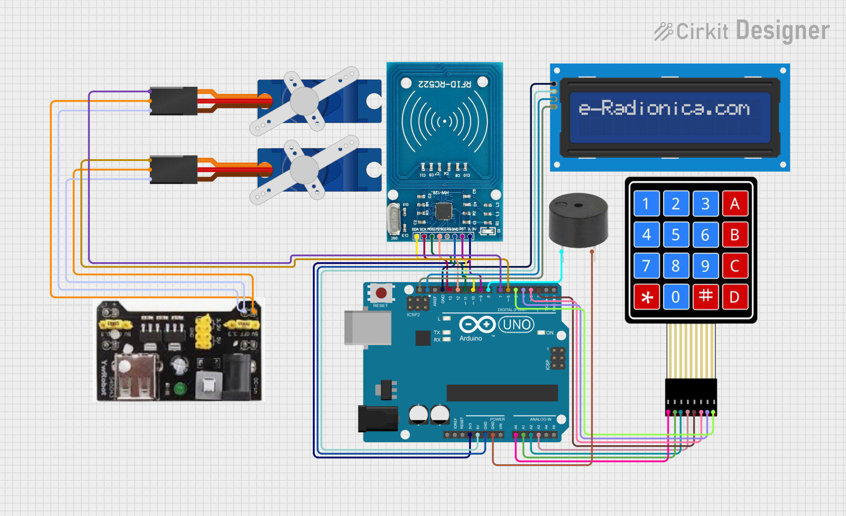
Example: Connecting MIBL 0520 to an Arduino UNO

The MIBL 0520 can be interfaced with an Arduino UNO for signal processing or data conversion tasks. Below is an example code snippet:

// Example: Interfacing MIBL 0520 with Arduino UNO
// This code demonstrates how to send a clock signal and read the output signal.

const int clkPin = 9;  // Pin 9 connected to CLK pin of MIBL 0520
const int csPin = 10;  // Pin 10 connected to CS pin of MIBL 0520
const int outPin = A0; // Analog pin A0 connected to OUT pin of MIBL 0520

void setup() {
  pinMode(clkPin, OUTPUT); // Set CLK pin as output
  pinMode(csPin, OUTPUT);  // Set CS pin as output
  digitalWrite(csPin, HIGH); // Disable the IC initially
  Serial.begin(9600); // Initialize serial communication
}

void loop() {
  digitalWrite(csPin, LOW); // Enable the IC
  digitalWrite(clkPin, HIGH); // Send a clock pulse
  delayMicroseconds(10); // Short delay for clock pulse
  digitalWrite(clkPin, LOW);

  int outputValue = analogRead(outPin); // Read the output signal
  Serial.println(outputValue); // Print the output value to the Serial Monitor

  delay(100); // Wait before the next reading
}

Troubleshooting and FAQs

Common Issues and Solutions

  1. No Output Signal:

    • Ensure the IC is powered correctly (check Vcc and GND connections).
    • Verify that the CS pin is pulled low to enable the IC.
    • Check the input signal levels and ensure they are within the IC's operating range.
  2. Excessive Noise in Output:

    • Use decoupling capacitors near the power supply pins.
    • Minimize the length of input and output signal wires.
    • Ensure proper grounding in the circuit.
  3. Overheating:

    • Verify that the supply voltage does not exceed the maximum rating.
    • Check for short circuits or incorrect connections.
  4. Clock Signal Issues:

    • Ensure the clock frequency matches the IC's requirements.
    • Use a stable clock source to avoid synchronization problems.

FAQs

Q1: Can the MIBL 0520 operate without a clock signal?
A1: No, the MIBL 0520 requires a clock signal on the CLK pin for proper operation.

Q2: What happens if the CS pin is left floating?
A2: The IC may behave unpredictably. Always pull the CS pin high or low as needed.

Q3: Can I use the MIBL 0520 with a 3.3V power supply?
A3: Yes, the IC supports a supply voltage range of 2.7V to 5.5V, so 3.3V is within the acceptable range.

Q4: Is the MIBL 0520 suitable for high-frequency applications?
A4: The IC supports signal bandwidths up to 20 MHz, making it suitable for many high-frequency applications.