Cirkit Designer Logo
Cirkit Designer
Your all-in-one circuit design IDE
Home / 
Component Documentation

How to Use ESP 32 Wroom Dev Kit: Examples, Pinouts, and Specs

Image of ESP 32 Wroom Dev Kit
Cirkit Designer LogoDesign with ESP 32 Wroom Dev Kit in Cirkit Designer

Introduction

The ESP32-WROOM Dev Kit is a versatile development board that features the ESP32-WROOM-32 module. This module is a powerful and highly integrated solution that combines Wi-Fi and Bluetooth connectivity, making it ideal for a wide range of Internet of Things (IoT) projects and applications. The ESP32-WROOM-32 is known for its low-power consumption, high performance, and extensive GPIO capabilities.

Common applications of the ESP32-WROOM Dev Kit include:

  • Smart home devices
  • Wearable electronics
  • Wireless sensors
  • Industrial automation
  • Robotics
  • Environmental monitoring

Explore Projects Built with ESP 32 Wroom Dev Kit

Use Cirkit Designer to design, explore, and prototype these projects online. Some projects support real-time simulation. Click "Open Project" to start designing instantly!
ESP32-Based GPS Tracker with SD Card Logging and Barometric Sensor
Image of gps projekt circuit: A project utilizing ESP 32 Wroom Dev Kit in a practical application
This circuit features an ESP32 Wroom Dev Kit as the main microcontroller, interfaced with an MPL3115A2 sensor for pressure and temperature readings, and a Neo 6M GPS module for location tracking. The ESP32 is also connected to an SD card reader for data logging purposes. A voltage regulator is used to step down the USB power supply to 3.3V, which powers the ESP32, the sensor, and the SD card reader.
Cirkit Designer LogoOpen Project in Cirkit Designer
ESP32 and Arduino UNO Serial Communication Interface
Image of ESP32 Arduino COM SErial: A project utilizing ESP 32 Wroom Dev Kit in a practical application
This circuit integrates an ESP32 Wroom Dev Kit and an Arduino UNO, connected via their TXD/RXD pins for serial communication and sharing a common ground. Both microcontrollers are programmed with basic setup and loop functions, indicating a potential for further development of communication or control tasks.
Cirkit Designer LogoOpen Project in Cirkit Designer
ESP32-Based Vibration Motor Controller with I2C IO Expansion
Image of VIBRATYION: A project utilizing ESP 32 Wroom Dev Kit in a practical application
This circuit features an ESP32 Wroom Dev Kit microcontroller interfaced with an MCP23017 I/O expansion board via I2C communication, utilizing GPIO 21 and GPIO 22 for SDA and SCL lines, respectively. A vibration motor is controlled by an NPN transistor acting as a switch, with a diode for back EMF protection and a resistor to limit base current. The ESP32 can control the motor by sending signals to the MCP23017, which then interfaces with the transistor to turn the motor on or off.
Cirkit Designer LogoOpen Project in Cirkit Designer
Raspberry Pi Pico and ESP32 Wi-Fi Controlled Sensor Interface
Image of pico_esp32: A project utilizing ESP 32 Wroom Dev Kit in a practical application
This circuit integrates a Raspberry Pi Pico and an ESP32 Wroom Dev Kit, interconnected through various GPIO pins and resistors, to enable communication and control between the two microcontrollers. The ESP32 is powered by a 3.3V supply and shares ground with the Raspberry Pi Pico, while specific GPIO pins are used for data exchange. The provided code sketches for the Raspberry Pi Pico suggest a framework for further development of the system's functionality.
Cirkit Designer LogoOpen Project in Cirkit Designer

Explore Projects Built with ESP 32 Wroom Dev Kit

Use Cirkit Designer to design, explore, and prototype these projects online. Some projects support real-time simulation. Click "Open Project" to start designing instantly!
Image of gps projekt circuit: A project utilizing ESP 32 Wroom Dev Kit in a practical application
ESP32-Based GPS Tracker with SD Card Logging and Barometric Sensor
This circuit features an ESP32 Wroom Dev Kit as the main microcontroller, interfaced with an MPL3115A2 sensor for pressure and temperature readings, and a Neo 6M GPS module for location tracking. The ESP32 is also connected to an SD card reader for data logging purposes. A voltage regulator is used to step down the USB power supply to 3.3V, which powers the ESP32, the sensor, and the SD card reader.
Cirkit Designer LogoOpen Project in Cirkit Designer
Image of ESP32 Arduino COM SErial: A project utilizing ESP 32 Wroom Dev Kit in a practical application
ESP32 and Arduino UNO Serial Communication Interface
This circuit integrates an ESP32 Wroom Dev Kit and an Arduino UNO, connected via their TXD/RXD pins for serial communication and sharing a common ground. Both microcontrollers are programmed with basic setup and loop functions, indicating a potential for further development of communication or control tasks.
Cirkit Designer LogoOpen Project in Cirkit Designer
Image of VIBRATYION: A project utilizing ESP 32 Wroom Dev Kit in a practical application
ESP32-Based Vibration Motor Controller with I2C IO Expansion
This circuit features an ESP32 Wroom Dev Kit microcontroller interfaced with an MCP23017 I/O expansion board via I2C communication, utilizing GPIO 21 and GPIO 22 for SDA and SCL lines, respectively. A vibration motor is controlled by an NPN transistor acting as a switch, with a diode for back EMF protection and a resistor to limit base current. The ESP32 can control the motor by sending signals to the MCP23017, which then interfaces with the transistor to turn the motor on or off.
Cirkit Designer LogoOpen Project in Cirkit Designer
Image of pico_esp32: A project utilizing ESP 32 Wroom Dev Kit in a practical application
Raspberry Pi Pico and ESP32 Wi-Fi Controlled Sensor Interface
This circuit integrates a Raspberry Pi Pico and an ESP32 Wroom Dev Kit, interconnected through various GPIO pins and resistors, to enable communication and control between the two microcontrollers. The ESP32 is powered by a 3.3V supply and shares ground with the Raspberry Pi Pico, while specific GPIO pins are used for data exchange. The provided code sketches for the Raspberry Pi Pico suggest a framework for further development of the system's functionality.
Cirkit Designer LogoOpen Project in Cirkit Designer

Technical Specifications

Key Technical Details

  • Processor: Tensilica Xtensa® Dual-Core 32-bit LX6 microprocessor
  • Operating Voltage: 3.3V
  • Input Voltage: 5V via micro USB or Vin pin
  • Digital I/O Pins: 39 (of which 34 are programmable)
  • Analog Input Pins: 18
  • Flash Memory: 4MB
  • SRAM: 520 KB
  • Wi-Fi: 802.11 b/g/n
  • Bluetooth: v4.2 BR/EDR and BLE
  • Clock Frequency: Up to 240MHz
  • Operating Temperature: -40°C to +125°C

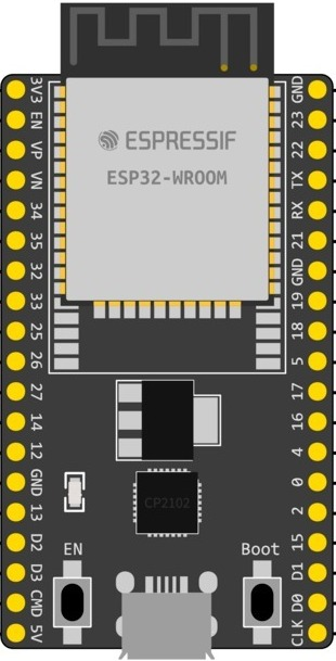
Pin Configuration and Descriptions

Pin Number Function Description
1 GND Ground
2 3V3 3.3V power supply input
3 EN Chip enable. Active high.
4 VP GPIO36, ADC1_CH0, Sensor VP
5 VN GPIO39, ADC1_CH3, Sensor VN
... ... ...
n GND Ground

Note: This table is not exhaustive and only includes a selection of pins for illustration.

Usage Instructions

Integrating with a Circuit

To use the ESP32-WROOM Dev Kit in a circuit:

  1. Powering the Device: Connect a 5V power supply to the micro USB port or Vin pin.
  2. Programming: Use the micro USB port to connect the Dev Kit to a computer for programming.
  3. GPIO Connections: Connect sensors, actuators, or other peripherals to the GPIO pins as required for your project.

Important Considerations and Best Practices

  • Power Supply: Ensure that the power supply is stable and within the recommended voltage range.
  • Antenna: Keep the antenna area of the module clear from metal components to ensure proper wireless communication.
  • ESD Precautions: Handle the board with care to avoid electrostatic discharge damage.
  • Firmware Updates: Regularly update the firmware to the latest version for optimal performance and security.

Troubleshooting and FAQs

Common Issues

  • Device Not Booting: Ensure that the power supply is connected correctly and the EN pin is pulled high.
  • Wi-Fi/Bluetooth Not Working: Check that the antenna area is not obstructed and that the correct drivers are installed.
  • Programming Errors: Verify the correct board settings in the IDE and that the USB drivers are up to date.

Solutions and Tips

  • Boot Mode: If the device is not entering the correct boot mode, check the boot mode configuration pins (IO0, IO2, etc.).
  • Signal Integrity: Use impedance-matched traces for high-frequency signals, especially for the antenna connections.
  • Firmware Flashing: Use the provided tools and follow the manufacturer's instructions for flashing firmware.

FAQs

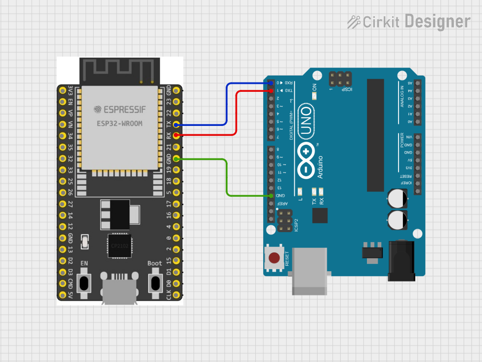
Q: Can I use the ESP32-WROOM Dev Kit with Arduino IDE? A: Yes, the ESP32-WROOM Dev Kit is compatible with the Arduino IDE. You will need to install the ESP32 board package using the Boards Manager.

Q: What is the maximum current draw for the GPIO pins? A: The maximum current draw for each GPIO pin is 12 mA.

Q: How do I enable Bluetooth functionality? A: Bluetooth can be enabled through the software using the appropriate libraries and initializing the Bluetooth stack.

Example Code for Arduino UNO

Below is a simple example of how to blink an LED connected to the ESP32-WROOM Dev Kit using the Arduino IDE:

// Define the LED pin
const int LED_PIN = 2; // Use GPIO2 for the LED

// Setup function runs once at the start
void setup() {
  // Initialize the LED pin as an output
  pinMode(LED_PIN, OUTPUT);
}

// Loop function runs repeatedly
void loop() {
  digitalWrite(LED_PIN, HIGH); // Turn the LED on
  delay(1000);                // Wait for a second
  digitalWrite(LED_PIN, LOW);  // Turn the LED off
  delay(1000);                // Wait for a second
}

Note: Before uploading the code, select the correct board and port in the Arduino IDE.

This documentation provides an overview of the ESP32-WROOM Dev Kit and should serve as a starting point for users looking to integrate this module into their projects. For more detailed information, refer to the manufacturer's datasheets and technical references.