Cirkit Designer Logo
Cirkit Designer
Your all-in-one circuit design IDE
Home / 
Component Documentation

How to Use Step Down Converter USB (12-24V): Examples, Pinouts, and Specs

Image of Step Down Converter USB (12-24V)
Cirkit Designer LogoDesign with Step Down Converter USB (12-24V) in Cirkit Designer

Introduction

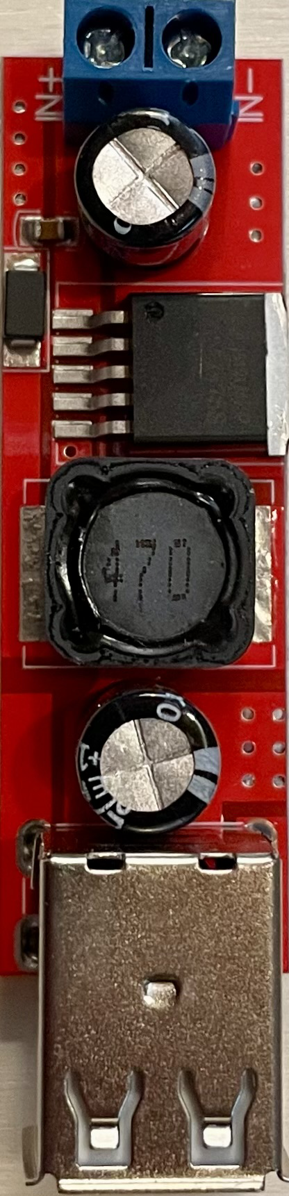
The Step Down Converter USB module is an electronic device designed to convert higher DC input voltages, typically in the range of 12-24V, to a lower, stable DC output voltage suitable for charging USB devices. This module is commonly used in automotive applications, where the electrical system provides a nominal 12V or 24V, which needs to be stepped down to the 5V required by USB-powered devices such as smartphones, tablets, and GPS units.

Explore Projects Built with Step Down Converter USB (12-24V)

Use Cirkit Designer to design, explore, and prototype these projects online. Some projects support real-time simulation. Click "Open Project" to start designing instantly!
USB Power Supply with Overcurrent Protection
Image of USB Charging port: A project utilizing Step Down Converter USB (12-24V) in a practical application
This circuit is designed to step down voltage from a 12V battery to a lower voltage suitable for USB devices. It includes a buck converter connected to the battery through a fuse and fuse holder for overcurrent protection. The output of the buck converter is connected to a USB female port, providing a regulated power supply for USB-powered devices.
Cirkit Designer LogoOpen Project in Cirkit Designer
Battery-Powered DC-DC Converter System for Multi-Voltage Power Distribution
Image of test 1 ih: A project utilizing Step Down Converter USB (12-24V) in a practical application
This circuit converts a 38.5V battery output to multiple lower voltage levels using a series of DC-DC converters and a power module. It includes an emergency stop switch for safety and distributes power to various components such as a relay module, USB ports, and a bus servo adaptor.
Cirkit Designer LogoOpen Project in Cirkit Designer
Battery-Powered UPS with Step-Down Buck Converter and BMS
Image of Mini ups: A project utilizing Step Down Converter USB (12-24V) in a practical application
This circuit is a power management system that steps down a 240V AC input to a lower DC voltage using a buck converter, which then powers a 40W UPS. The UPS is controlled by a rocker switch and is backed up by a battery management system (BMS) connected to three 3.7V batteries in series, ensuring continuous power supply.
Cirkit Designer LogoOpen Project in Cirkit Designer
AC to DC Micro USB Power Supply with Buck Converter
Image of ac: A project utilizing Step Down Converter USB (12-24V) in a practical application
This circuit is designed to convert AC power to regulated DC power. An AC source feeds a power transformer that steps down the voltage, which is then rectified by a bridge rectifier to produce a pulsating DC. This DC is further converted to a stable DC output by a step-down buck converter, which then provides power through a Micro USB connector.
Cirkit Designer LogoOpen Project in Cirkit Designer

Explore Projects Built with Step Down Converter USB (12-24V)

Use Cirkit Designer to design, explore, and prototype these projects online. Some projects support real-time simulation. Click "Open Project" to start designing instantly!
Image of USB Charging port: A project utilizing Step Down Converter USB (12-24V) in a practical application
USB Power Supply with Overcurrent Protection
This circuit is designed to step down voltage from a 12V battery to a lower voltage suitable for USB devices. It includes a buck converter connected to the battery through a fuse and fuse holder for overcurrent protection. The output of the buck converter is connected to a USB female port, providing a regulated power supply for USB-powered devices.
Cirkit Designer LogoOpen Project in Cirkit Designer
Image of test 1 ih: A project utilizing Step Down Converter USB (12-24V) in a practical application
Battery-Powered DC-DC Converter System for Multi-Voltage Power Distribution
This circuit converts a 38.5V battery output to multiple lower voltage levels using a series of DC-DC converters and a power module. It includes an emergency stop switch for safety and distributes power to various components such as a relay module, USB ports, and a bus servo adaptor.
Cirkit Designer LogoOpen Project in Cirkit Designer
Image of Mini ups: A project utilizing Step Down Converter USB (12-24V) in a practical application
Battery-Powered UPS with Step-Down Buck Converter and BMS
This circuit is a power management system that steps down a 240V AC input to a lower DC voltage using a buck converter, which then powers a 40W UPS. The UPS is controlled by a rocker switch and is backed up by a battery management system (BMS) connected to three 3.7V batteries in series, ensuring continuous power supply.
Cirkit Designer LogoOpen Project in Cirkit Designer
Image of ac: A project utilizing Step Down Converter USB (12-24V) in a practical application
AC to DC Micro USB Power Supply with Buck Converter
This circuit is designed to convert AC power to regulated DC power. An AC source feeds a power transformer that steps down the voltage, which is then rectified by a bridge rectifier to produce a pulsating DC. This DC is further converted to a stable DC output by a step-down buck converter, which then provides power through a Micro USB connector.
Cirkit Designer LogoOpen Project in Cirkit Designer

Common Applications and Use Cases

  • Charging USB devices in vehicles
  • Powering USB devices from a higher voltage battery bank
  • DIY electronics projects requiring USB power from a higher voltage source

Technical Specifications

Key Technical Details

  • Input Voltage: 12-24V DC
  • Output Voltage: 5V DC
  • Output Current: Up to 3A (depending on model)
  • Conversion Efficiency: Up to 95%
  • Operating Temperature: -40°C to +85°C

Pin Configuration and Descriptions

Pin Number Description Notes
1 Input Voltage (VIN) Connect to 12-24V power source
2 Ground (GND) Common ground for input/output
3 USB Output (+5V) Connect to USB device VCC
4 USB Output (GND) Connect to USB device GND

Usage Instructions

How to Use the Component in a Circuit

  1. Power Source Connection: Connect the positive terminal of your 12-24V power source to the VIN pin, and the negative terminal to the GND pin.
  2. Device Connection: Plug your USB device into the USB port of the module.
  3. Mounting: Secure the module to your project or vehicle, ensuring it is properly insulated from any conductive surfaces.

Important Considerations and Best Practices

  • Voltage Range: Do not exceed the specified input voltage range to avoid damage.
  • Heat Dissipation: Ensure adequate ventilation around the module, as it may generate heat during operation.
  • Load Capacity: Do not exceed the maximum output current rating.
  • Short Circuit Protection: Always check for short circuits in your wiring before powering the module.

Troubleshooting and FAQs

Common Issues

  • USB Device Not Charging: Ensure the input voltage is within the specified range and connections are secure.
  • Module Overheating: Check if the module is overloaded or lacks proper ventilation.
  • Intermittent Power: Inspect for loose connections or intermittent contact in the wiring.

Solutions and Tips for Troubleshooting

  • Input Voltage Check: Use a multimeter to verify the input voltage is within the 12-24V range.
  • Connection Inspection: Recheck all connections for proper contact and secure them with appropriate connectors.
  • Load Reduction: If overheating, reduce the load on the module or improve cooling.

FAQs

Q: Can I use this module to power non-USB devices? A: Yes, as long as the device operates at 5V and does not draw more current than the module's rating.

Q: Is the output voltage adjustable? A: No, this module provides a fixed 5V output suitable for USB devices.

Q: Does this module offer protection against reverse polarity? A: This varies by model. Check the specific model's datasheet for protection features.

Example Arduino UNO Connection

// No specific code is required for the Step Down Converter USB module
// as it is a power supply component. However, you can monitor the
// output voltage using an Arduino UNO by connecting an analog pin
// to the USB output and reading the voltage.

const int analogPin = A0; // Connect to the USB output (+5V) through a voltage divider

void setup() {
  Serial.begin(9600);
}

void loop() {
  int sensorValue = analogRead(analogPin);
  float voltage = sensorValue * (5.0 / 1023.0); // Convert the reading to voltage
  Serial.print("USB Output Voltage: ");
  Serial.println(voltage);
  delay(1000); // Wait for a second between readings
}

Note: When connecting the USB output to an analog pin, ensure you use a voltage divider to bring the voltage within the safe range for the Arduino analog input (0-5V).