
How to Use BMI160 Accelerometer Gyro - 6DOF sensor: Examples, Pinouts, and Specs
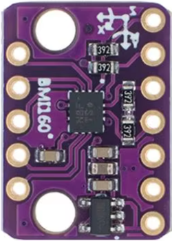
 Design with BMI160 Accelerometer Gyro - 6DOF sensor in Cirkit Designer
Introduction
The BMI160 is a high-performance 6 Degrees of Freedom (6DOF) sensor manufactured by Winwin. It integrates a 3-axis accelerometer and a 3-axis gyroscope into a single compact package, making it ideal for motion tracking and orientation detection. This sensor is widely used in applications such as smartphones, drones, wearable devices, gaming controllers, and robotics.
The BMI160 is designed for low power consumption, making it suitable for battery-powered devices. It communicates via I2C or SPI interfaces, providing flexibility for integration into various systems.
Explore Projects Built with BMI160 Accelerometer Gyro - 6DOF sensor
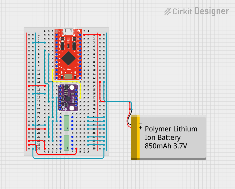 Open Project in Cirkit Designer
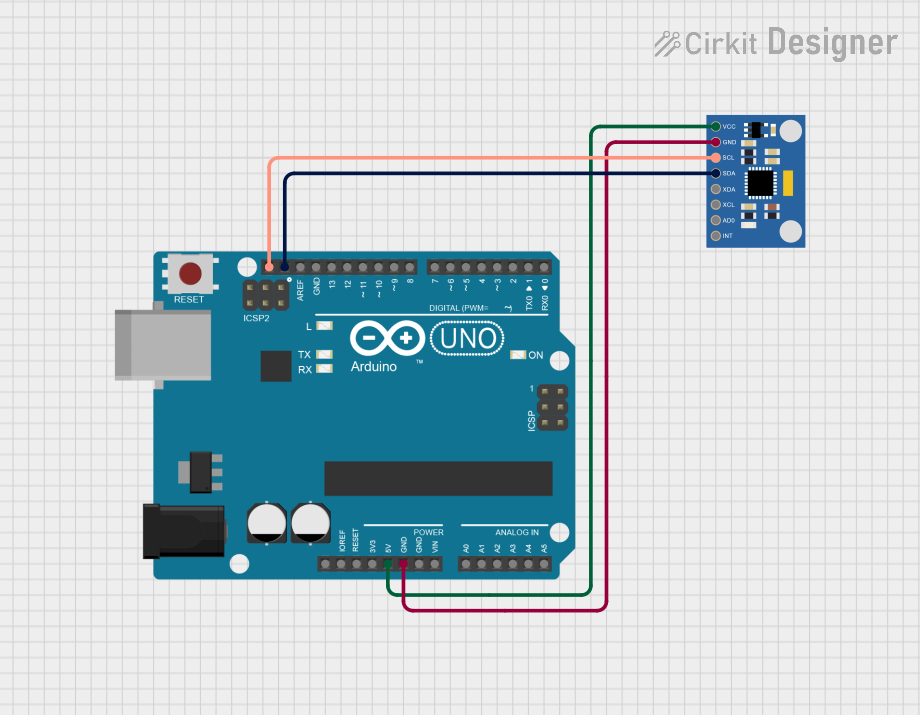 Open Project in Cirkit Designer
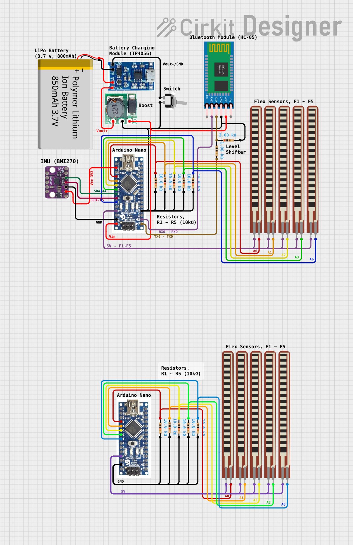 Open Project in Cirkit Designer
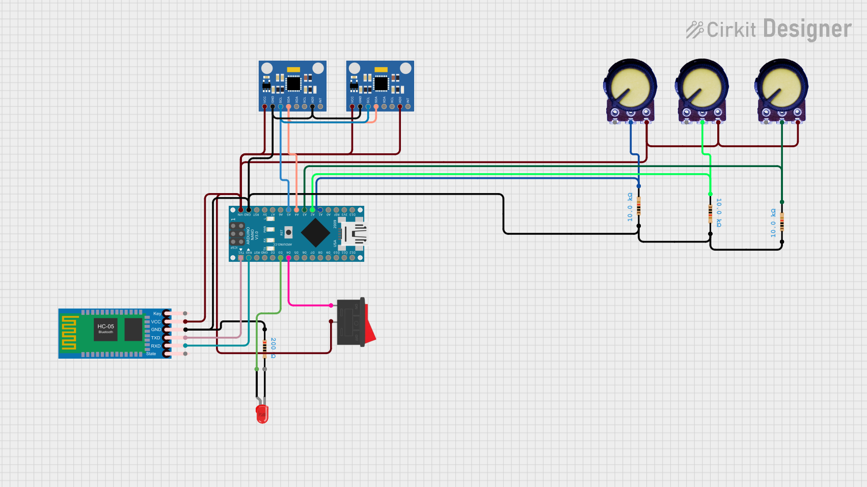 Open Project in Cirkit Designer
Explore Projects Built with BMI160 Accelerometer Gyro - 6DOF sensor
Open Project in Cirkit DesignerOpen Project in Cirkit DesignerOpen Project in Cirkit DesignerOpen Project in Cirkit DesignerTechnical Specifications
Below are the key technical details of the BMI160 sensor:
| Parameter | Value |
|---|---|
| Manufacturer | Winwin |
| Part ID | BMI160 |
| Sensor Type | 3-axis accelerometer + 3-axis gyroscope |
| Degrees of Freedom (DOF) | 6 |
| Operating Voltage | 1.8V to 3.6V |
| Communication Interfaces | I2C, SPI |
| Accelerometer Range | ±2g, ±4g, ±8g, ±16g |
| Gyroscope Range | ±125°/s, ±250°/s, ±500°/s, ±1000°/s, ±2000°/s |
| Power Consumption (Typical) | 925 µA (accelerometer + gyroscope) |
| Operating Temperature Range | -40°C to +85°C |
| Package Type | LGA-14 (2.5mm x 3.0mm x 0.83mm) |
Pin Configuration and Descriptions
The BMI160 comes in a 14-pin LGA package. Below is the pin configuration:
| Pin Number | Pin Name | Description |
|---|---|---|
| 1 | GND | Ground |
| 2 | VDDIO | I/O Voltage Supply (1.2V to 3.6V) |
| 3 | VDD | Core Voltage Supply (1.8V to 3.6V) |
| 4 | CS | Chip Select (SPI mode) |
| 5 | SDO/SA0 | SPI Data Out / I2C Address Selection |
| 6 | SCL/SCLK | I2C Clock / SPI Clock |
| 7 | SDA/SDI | I2C Data / SPI Data Input |
| 8 | INT1 | Interrupt 1 Output |
| 9 | INT2 | Interrupt 2 Output |
| 10-14 | NC | Not Connected |
Usage Instructions
How to Use the BMI160 in a Circuit
- Power Supply: Connect the VDD pin to a 1.8V to 3.6V power source and the VDDIO pin to the desired I/O voltage (1.2V to 3.6V). Connect the GND pin to the ground of your circuit.
- Communication Interface: Choose between I2C or SPI for communication:
- For I2C, connect the SCL and SDA pins to the corresponding I2C lines on your microcontroller. Use pull-up resistors (typically 4.7kΩ) on both lines.
- For SPI, connect the SCLK, SDI, and CS pins to the corresponding SPI lines on your microcontroller.
- Interrupts: If needed, connect the INT1 and/or INT2 pins to your microcontroller for motion detection or other interrupt-driven events.
- Address Selection (I2C): Use the SDO/SA0 pin to set the I2C address. Connect it to GND for the default address (0x68) or to VDDIO for the alternate address (0x69).
Important Considerations and Best Practices
- Bypass Capacitor: Place a 0.1µF decoupling capacitor close to the VDD pin to reduce noise.
- PCB Layout: Ensure proper grounding and minimize noise on the communication lines.
- Orientation: Mount the sensor in the correct orientation as per your application to ensure accurate readings.
- Initialization: Configure the sensor's registers during initialization to set the desired accelerometer and gyroscope ranges, output data rates, and power modes.
Example Code for Arduino UNO
Below is an example of how to interface the BMI160 with an Arduino UNO using the I2C interface:
#include <Wire.h>

// BMI160 I2C address (default: 0x68)
#define BMI160_I2C_ADDR 0x68

// BMI160 register addresses
#define BMI160_CHIP_ID_REG 0x00
#define BMI160_ACC_X_LSB 0x12

void setup() {
  Wire.begin(); // Initialize I2C communication
  Serial.begin(9600); // Initialize serial communication for debugging

  // Check if the BMI160 is connected
  Wire.beginTransmission(BMI160_I2C_ADDR);
  Wire.write(BMI160_CHIP_ID_REG); // Request the chip ID register
  Wire.endTransmission();
  Wire.requestFrom(BMI160_I2C_ADDR, 1);

  if (Wire.available()) {
    uint8_t chipID = Wire.read();
    if (chipID == 0xD1) { // Expected chip ID for BMI160
      Serial.println("BMI160 detected!");
    } else {
      Serial.print("Unexpected chip ID: 0x");
      Serial.println(chipID, HEX);
    }
  } else {
    Serial.println("BMI160 not detected. Check connections.");
  }
}

void loop() {
  // Read accelerometer data
  Wire.beginTransmission(BMI160_I2C_ADDR);
  Wire.write(BMI160_ACC_X_LSB); // Request accelerometer X-axis LSB register
  Wire.endTransmission();
  Wire.requestFrom(BMI160_I2C_ADDR, 6); // Read 6 bytes (X, Y, Z axes)

  if (Wire.available() == 6) {
    int16_t accX = Wire.read() | (Wire.read() << 8);
    int16_t accY = Wire.read() | (Wire.read() << 8);
    int16_t accZ = Wire.read() | (Wire.read() << 8);

    Serial.print("Accel X: ");
    Serial.print(accX);
    Serial.print(" Y: ");
    Serial.print(accY);
    Serial.print(" Z: ");
    Serial.println(accZ);
  }

  delay(500); // Delay for readability
}
Troubleshooting and FAQs
Common Issues
Sensor Not Detected:
- Ensure the I2C or SPI connections are correct.
- Verify the I2C address (default is 0x68 unless SDO/SA0 is connected to VDDIO).
- Check the power supply voltage levels (VDD and VDDIO).
Incorrect or No Data:
- Confirm that the sensor is properly initialized with the correct register settings.
- Check for noise or interference on the communication lines.
High Power Consumption:
- Ensure the sensor is configured in low-power mode if applicable.
- Disable unused features such as interrupts or FIFO.
Tips for Troubleshooting
- Use a logic analyzer or oscilloscope to monitor the I2C/SPI signals.
- Double-check the pull-up resistors on the I2C lines.
- Refer to the BMI160 datasheet for detailed register descriptions and configuration options.
By following this documentation, you should be able to successfully integrate and use the BMI160 sensor in your projects.