Cirkit Designer Logo
Cirkit Designer
Your all-in-one circuit design IDE
Home / 
Component Documentation

How to Use Snubber Circuit Module: Examples, Pinouts, and Specs

Image of Snubber Circuit Module
Cirkit Designer LogoDesign with Snubber Circuit Module in Cirkit Designer

Introduction

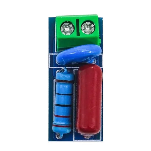
The Snubber Circuit Module (Manufacturer Part ID: ST2010SM0751) by SHARVI TECHNOLOGIES (OPC) PRIVATE LIMITED is a compact and efficient solution designed to protect electronic components from voltage spikes and transients. By absorbing excess energy, the module ensures stable operation and prevents potential damage to sensitive components in a circuit.

This module is commonly used in applications involving inductive loads, such as motors, relays, and transformers, where voltage spikes are prevalent. It is also widely employed in power electronics, industrial automation, and motor control systems.

Explore Projects Built with Snubber Circuit Module

Use Cirkit Designer to design, explore, and prototype these projects online. Some projects support real-time simulation. Click "Open Project" to start designing instantly!
IoT-Enabled Environmental Monitoring System with NUCLEO-F303RE and ESP8266
Image of GAS LEAKAGE DETECTION: A project utilizing Snubber Circuit Module in a practical application
This circuit features a NUCLEO-F303RE microcontroller board interfaced with various modules for sensing, actuation, and communication. It includes an MQ-2 gas sensor for detecting combustible gases, a buzzer for audible alerts, and a relay for controlling high-power devices. Additionally, the circuit uses an ESP8266 WiFi module for wireless connectivity and an I2C LCD display for user interface and data display.
Cirkit Designer LogoOpen Project in Cirkit Designer
Arduino Nano Controlled Relay System with Safety Interlocks
Image of HYD: A project utilizing Snubber Circuit Module in a practical application
This circuit includes an Arduino Nano microcontroller interfaced with multiple pushbuttons, limit switches, an emergency stop, a 2-channel relay module, and a 1-channel relay module. The Arduino controls the relay modules based on inputs from the pushbuttons and limit switches, which likely serve as user interfaces and position or safety sensors. The circuit is powered by a 5V power supply unit (PSU), which is connected to an AC supply, and the emergency stop is configured to potentially interrupt the circuit for safety purposes.
Cirkit Designer LogoOpen Project in Cirkit Designer
ESP32-Based Safety and Tracking System with GSM and GPS
Image of GR project: A project utilizing Snubber Circuit Module in a practical application
This circuit features an ESP32 microcontroller interfaced with various sensors, modules, and a relay. The MQ-3 gas sensor and LDR (light-dependent resistor) provide environmental input to the ESP32, which can trigger a buzzer and control a relay based on predefined conditions. Additional components include a step-down module to regulate power, an LCD display for user interface, a SIM800L module for cellular connectivity, a GPS module for location tracking, and an ESP32-CAM for image capture, all integrated into a cohesive system possibly for a security or monitoring application.
Cirkit Designer LogoOpen Project in Cirkit Designer
Arduino UNO-Based Environmental Monitoring and Control System with GSM Notification
Image of PIR: A project utilizing Snubber Circuit Module in a practical application
This circuit is designed to monitor environmental conditions using gas and motion sensors, provide user feedback through an LCD display and a piezo buzzer, and control external devices via a relay. It also includes a GSM module for remote communication, a servomotor for actuation, and a fan for cooling or airflow, all managed by an Arduino UNO.
Cirkit Designer LogoOpen Project in Cirkit Designer

Explore Projects Built with Snubber Circuit Module

Use Cirkit Designer to design, explore, and prototype these projects online. Some projects support real-time simulation. Click "Open Project" to start designing instantly!
Image of GAS LEAKAGE DETECTION: A project utilizing Snubber Circuit Module in a practical application
IoT-Enabled Environmental Monitoring System with NUCLEO-F303RE and ESP8266
This circuit features a NUCLEO-F303RE microcontroller board interfaced with various modules for sensing, actuation, and communication. It includes an MQ-2 gas sensor for detecting combustible gases, a buzzer for audible alerts, and a relay for controlling high-power devices. Additionally, the circuit uses an ESP8266 WiFi module for wireless connectivity and an I2C LCD display for user interface and data display.
Cirkit Designer LogoOpen Project in Cirkit Designer
Image of HYD: A project utilizing Snubber Circuit Module in a practical application
Arduino Nano Controlled Relay System with Safety Interlocks
This circuit includes an Arduino Nano microcontroller interfaced with multiple pushbuttons, limit switches, an emergency stop, a 2-channel relay module, and a 1-channel relay module. The Arduino controls the relay modules based on inputs from the pushbuttons and limit switches, which likely serve as user interfaces and position or safety sensors. The circuit is powered by a 5V power supply unit (PSU), which is connected to an AC supply, and the emergency stop is configured to potentially interrupt the circuit for safety purposes.
Cirkit Designer LogoOpen Project in Cirkit Designer
Image of GR project: A project utilizing Snubber Circuit Module in a practical application
ESP32-Based Safety and Tracking System with GSM and GPS
This circuit features an ESP32 microcontroller interfaced with various sensors, modules, and a relay. The MQ-3 gas sensor and LDR (light-dependent resistor) provide environmental input to the ESP32, which can trigger a buzzer and control a relay based on predefined conditions. Additional components include a step-down module to regulate power, an LCD display for user interface, a SIM800L module for cellular connectivity, a GPS module for location tracking, and an ESP32-CAM for image capture, all integrated into a cohesive system possibly for a security or monitoring application.
Cirkit Designer LogoOpen Project in Cirkit Designer
Image of PIR: A project utilizing Snubber Circuit Module in a practical application
Arduino UNO-Based Environmental Monitoring and Control System with GSM Notification
This circuit is designed to monitor environmental conditions using gas and motion sensors, provide user feedback through an LCD display and a piezo buzzer, and control external devices via a relay. It also includes a GSM module for remote communication, a servomotor for actuation, and a fan for cooling or airflow, all managed by an Arduino UNO.
Cirkit Designer LogoOpen Project in Cirkit Designer

Technical Specifications

Below are the key technical details of the Snubber Circuit Module:

Parameter Value
Manufacturer SHARVI TECHNOLOGIES (OPC) PRIVATE LIMITED
Part ID ST2010SM0751
Operating Voltage Range 24V to 400V AC/DC
Maximum Voltage Rating 600V
Maximum Current Rating 10A
Power Dissipation 0.75W
Capacitance Value 0.1µF
Resistance Value 75Ω
Operating Temperature -40°C to +85°C
Dimensions 20mm x 10mm x 5mm
Mounting Type PCB Mountable

Pin Configuration and Descriptions

The Snubber Circuit Module has two pins for easy integration into circuits. The pin configuration is as follows:

Pin Name Description
1 Input/Positive Connect to the positive terminal of the load or circuit.
2 Output/Negative Connect to the negative terminal of the load or circuit.

Usage Instructions

How to Use the Snubber Circuit Module in a Circuit

  1. Identify the Load: Determine the inductive load (e.g., motor, relay, or transformer) in your circuit that requires protection from voltage spikes.
  2. Connect the Module:
    • Connect Pin 1 (Input/Positive) to the positive terminal of the load or the circuit.
    • Connect Pin 2 (Output/Negative) to the negative terminal of the load or the circuit.
  3. Verify Connections: Ensure that the module is securely connected and that the polarity is correct.
  4. Power On: Once the connections are verified, power on the circuit. The snubber module will automatically absorb voltage spikes and transients.

Important Considerations and Best Practices

  • Voltage Rating: Ensure that the operating voltage of the circuit does not exceed the module's maximum voltage rating of 600V.
  • Current Rating: The load current should not exceed the module's maximum current rating of 10A.
  • Placement: Place the module as close as possible to the inductive load to minimize the effects of voltage spikes.
  • Heat Dissipation: Ensure proper ventilation or heat sinking if the module operates near its maximum power dissipation of 0.75W.
  • Testing: Test the circuit under normal operating conditions to confirm the module's effectiveness in suppressing voltage spikes.

Example: Using the Snubber Circuit Module with an Arduino UNO

If you are using an Arduino UNO to control a relay, the Snubber Circuit Module can be connected across the relay's coil to suppress voltage spikes. Below is an example code snippet for controlling a relay with an Arduino UNO:

// Example: Controlling a relay with Arduino UNO
// Ensure the Snubber Circuit Module is connected across the relay coil
// to suppress voltage spikes and protect the circuit.

const int relayPin = 7; // Pin connected to the relay module

void setup() {
  pinMode(relayPin, OUTPUT); // Set relay pin as output
}

void loop() {
  digitalWrite(relayPin, HIGH); // Turn relay ON
  delay(1000);                  // Wait for 1 second
  digitalWrite(relayPin, LOW);  // Turn relay OFF
  delay(1000);                  // Wait for 1 second
}

Troubleshooting and FAQs

Common Issues Users Might Face

  1. Module Overheating:

    • Cause: Operating the module beyond its power dissipation or current rating.
    • Solution: Ensure the load current and power dissipation are within the specified limits. Improve ventilation or add a heat sink if necessary.
  2. Ineffective Voltage Spike Suppression:

    • Cause: Incorrect placement of the module or loose connections.
    • Solution: Place the module as close as possible to the inductive load and verify all connections.
  3. Module Damage:

    • Cause: Exceeding the maximum voltage or current rating.
    • Solution: Verify that the circuit's operating voltage and current are within the module's specifications.

FAQs

  1. Can the Snubber Circuit Module be used with DC circuits?

    • Yes, the module is compatible with both AC and DC circuits within the specified voltage range.
  2. What happens if the module is connected in reverse polarity?

    • Reverse polarity may damage the module. Always ensure correct polarity during installation.
  3. Can this module be used with high-frequency switching circuits?

    • Yes, the module is designed to handle high-frequency transients effectively.
  4. Is additional protection required for the module?

    • In most cases, no additional protection is required. However, for extreme conditions, consider using a fuse or circuit breaker.

By following this documentation, users can effectively integrate the Snubber Circuit Module (ST2010SM0751) into their projects, ensuring reliable and stable operation of their electronic circuits.