How to Use TAS5805M DAC: Examples, Pinouts, and Specs
Introduction
The TAS5805M is a high-performance digital-to-analog converter (DAC) with integrated Class-D amplification, designed by Texas Instruments. It is optimized for delivering high-quality audio output in a compact and power-efficient package. The TAS5805M supports multiple audio formats, including I2S and TDM, making it suitable for a wide range of audio applications.
Explore Projects Built with TAS5805M DAC
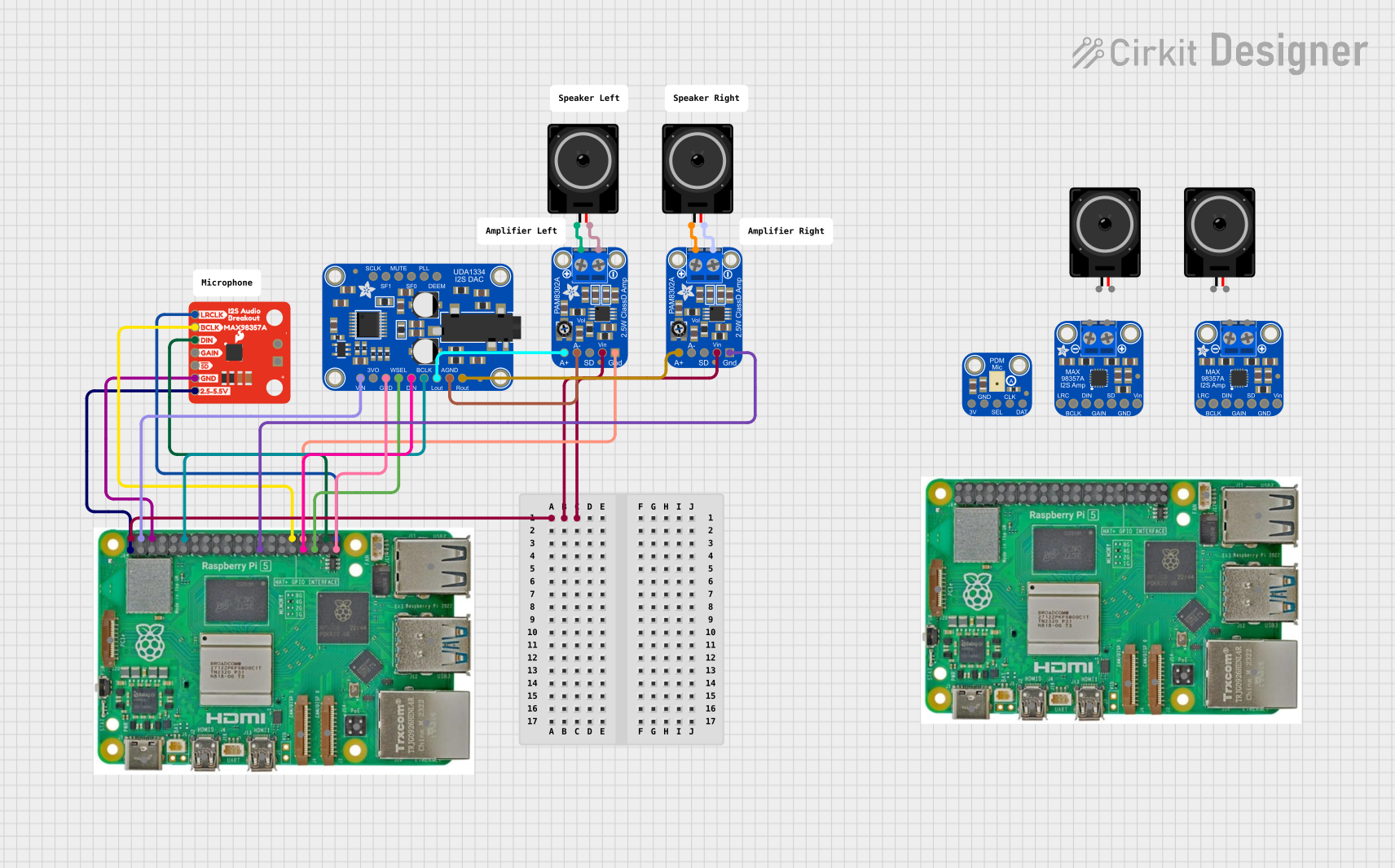
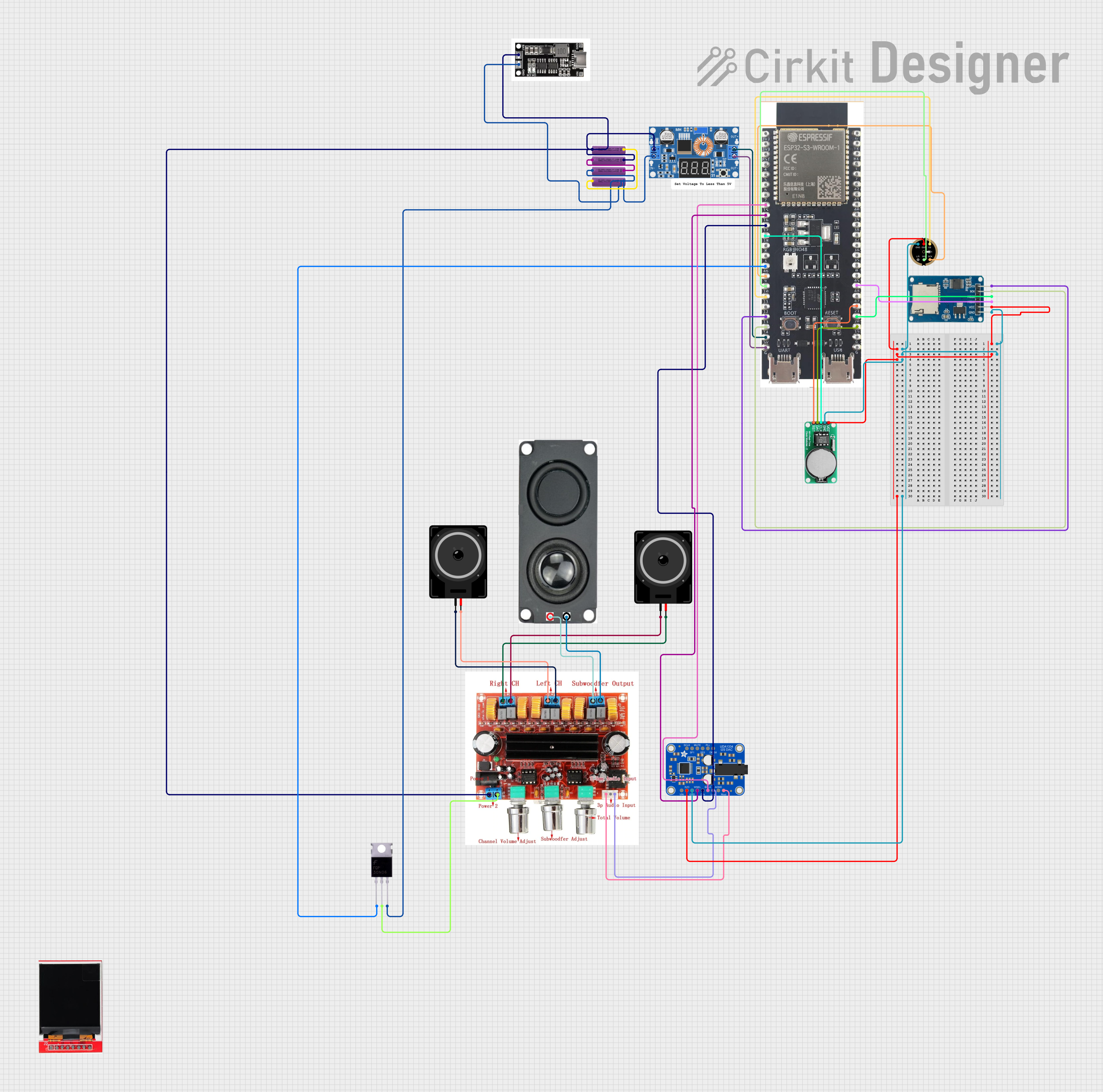


Explore Projects Built with TAS5805M DAC
Common Applications
- Wireless speakers and soundbars
- Smart home audio systems
- Automotive audio systems
- Portable audio devices
- Consumer electronics requiring high-fidelity sound
Technical Specifications
Key Technical Details
| Parameter | Value |
|---|---|
| Manufacturer Part ID | TAS5805MPWPR |
| Supply Voltage (VDD) | 4.5V to 26.4V |
| Output Power | Up to 23W per channel (4Ω, 24V, 10% THD) |
| Audio Input Formats | I2S, TDM |
| Signal-to-Noise Ratio (SNR) | 100 dB |
| Total Harmonic Distortion | 0.03% (1W, 1kHz, 8Ω) |
| Operating Temperature | -40°C to 85°C |
| Package Type | HTSSOP-24 |
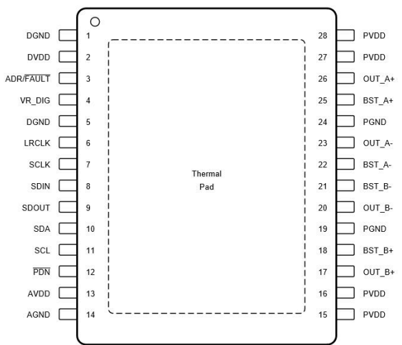
Pin Configuration and Descriptions
The TAS5805M comes in a 24-pin HTSSOP package. Below is the pin configuration:
| Pin Number | Pin Name | Description |
|---|---|---|
| 1 | PVDD | Power supply for the output stage |
| 2 | OUT_A | Positive output for channel A |
| 3 | OUT_A | Negative output for channel A |
| 4 | GND | Ground |
| 5 | OUT_B | Positive output for channel B |
| 6 | OUT_B | Negative output for channel B |
| 7 | PVDD | Power supply for the output stage |
| 8 | SDZ | Shutdown control (active low) |
| 9 | SCL | I2C clock input |
| 10 | SDA | I2C data input/output |
| 11 | MCLK | Master clock input |
| 12 | BCLK | Bit clock input |
| 13 | LRCLK | Left/right clock input |
| 14 | DIN | Digital audio input |
| 15 | DVDD | Digital power supply |
| 16 | AVDD | Analog power supply |
| 17 | GND | Ground |
| 18 | FAULTZ | Fault indicator (active low) |
| 19 | RESETZ | Reset control (active low) |
| 20 | GND | Ground |
| 21 | NC | No connection |
| 22 | NC | No connection |
| 23 | NC | No connection |
| 24 | NC | No connection |
Usage Instructions
How to Use the TAS5805M in a Circuit
- Power Supply: Connect the PVDD pin to a power supply within the range of 4.5V to 26.4V. Ensure proper decoupling capacitors are placed close to the power pins to minimize noise.
- Audio Input: Use the I2S or TDM interface to send digital audio signals to the DIN pin. Configure the BCLK, LRCLK, and MCLK pins according to the desired audio format and sampling rate.
- Amplifier Output: Connect the OUT_A and OUT_B pins to the speaker load. Ensure the load impedance matches the recommended value (e.g., 4Ω or 8Ω).
- Control Interface: Use the I2C interface (SCL and SDA pins) to configure the TAS5805M. This includes setting the volume, equalization, and other audio processing parameters.
- Shutdown and Reset: Use the SDZ and RESETZ pins to control the device's power state. Pull SDZ high to enable the device and RESETZ high to release the reset.
Important Considerations and Best Practices
- Thermal Management: The TAS5805M can generate heat during operation. Use a proper heat sink or ensure adequate PCB thermal design to dissipate heat effectively.
- Decoupling Capacitors: Place decoupling capacitors close to the power supply pins to reduce noise and improve stability.
- Speaker Protection: Use appropriate filters or protection circuits to prevent damage to the speakers in case of faults.
- I2C Configuration: Ensure the I2C pull-up resistors are correctly sized for the desired communication speed.
Example: Connecting TAS5805M to an Arduino UNO
Below is an example of how to configure the TAS5805M using an Arduino UNO via the I2C interface:
#include <Wire.h> // Include the Wire library for I2C communication

#define TAS5805M_I2C_ADDRESS 0x2C // Default I2C address of TAS5805M

void setup() {
  Wire.begin(); // Initialize I2C communication
  Serial.begin(9600); // Initialize serial communication for debugging

  // Configure TAS5805M
  Wire.beginTransmission(TAS5805M_I2C_ADDRESS);
  Wire.write(0x00); // Register address for device configuration
  Wire.write(0x01); // Example configuration value
  Wire.endTransmission();

  Serial.println("TAS5805M configured successfully.");
}

void loop() {
  // Main loop can be used to send additional commands or monitor status
}
Troubleshooting and FAQs
Common Issues and Solutions
No Audio Output
- Cause: Incorrect I2S or TDM configuration.
- Solution: Verify the BCLK, LRCLK, and MCLK signals. Ensure the audio format matches the TAS5805M's configuration.
Device Overheating
- Cause: Insufficient thermal management.
- Solution: Add a heat sink or improve PCB thermal design.
I2C Communication Failure
- Cause: Incorrect I2C address or wiring.
- Solution: Check the I2C address and ensure proper pull-up resistors are in place.
Distorted Audio Output
- Cause: Overdriven input signal or incorrect speaker load.
- Solution: Reduce the input signal amplitude and verify the speaker impedance.
FAQs
Q: Can the TAS5805M drive headphones directly?
A: No, the TAS5805M is designed for driving speakers. Use a dedicated headphone amplifier for headphones.Q: What is the maximum sampling rate supported?
A: The TAS5805M supports sampling rates up to 192 kHz.Q: Is the TAS5805M suitable for battery-powered devices?
A: Yes, its low power consumption makes it suitable for battery-powered applications.Q: Can I use the TAS5805M without an I2C controller?
A: The TAS5805M requires I2C communication for configuration. A microcontroller or similar device is necessary.