How to Use Load Cell 500g: Examples, Pinouts, and Specs
Introduction
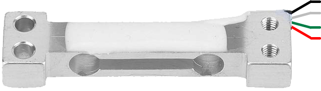
A Load Cell 500g is a type of sensor designed to measure weight or force. It operates by converting mechanical force applied to it into an electrical signal, which can then be processed by a microcontroller or other electronic devices. This specific load cell has a maximum capacity of 500 grams, making it ideal for applications requiring precise weight measurement in small-scale systems. Common use cases include kitchen scales, laboratory balances, and force measurement in robotics or automation systems.
Explore Projects Built with Load Cell 500g
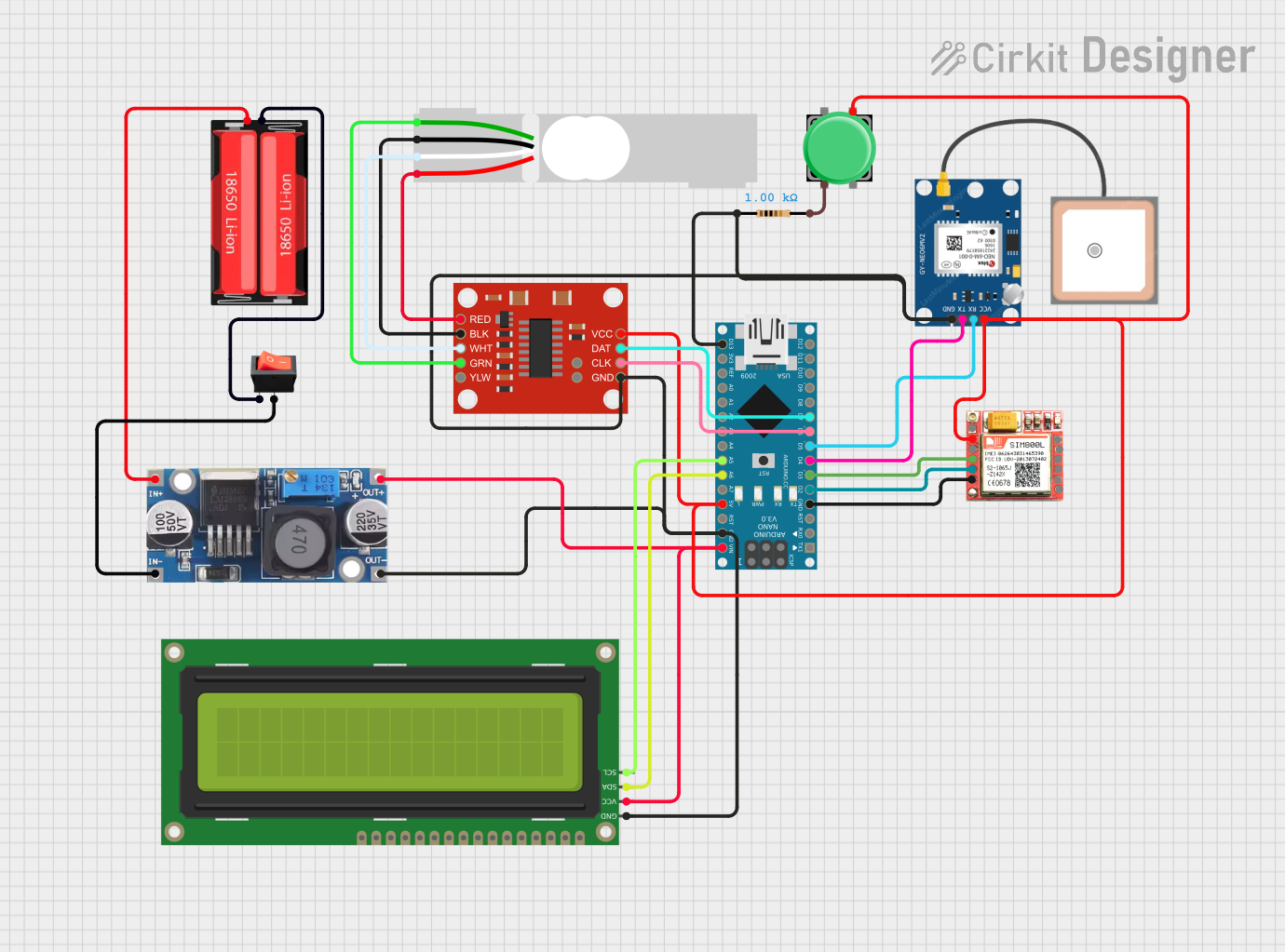
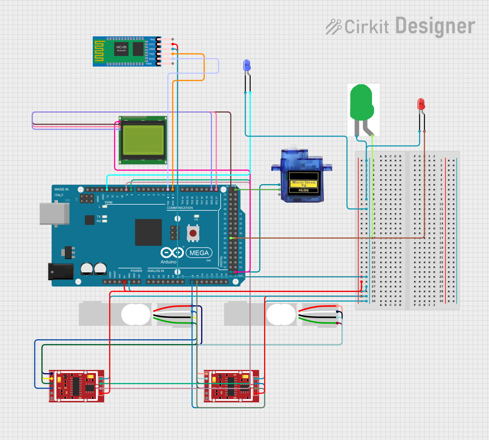
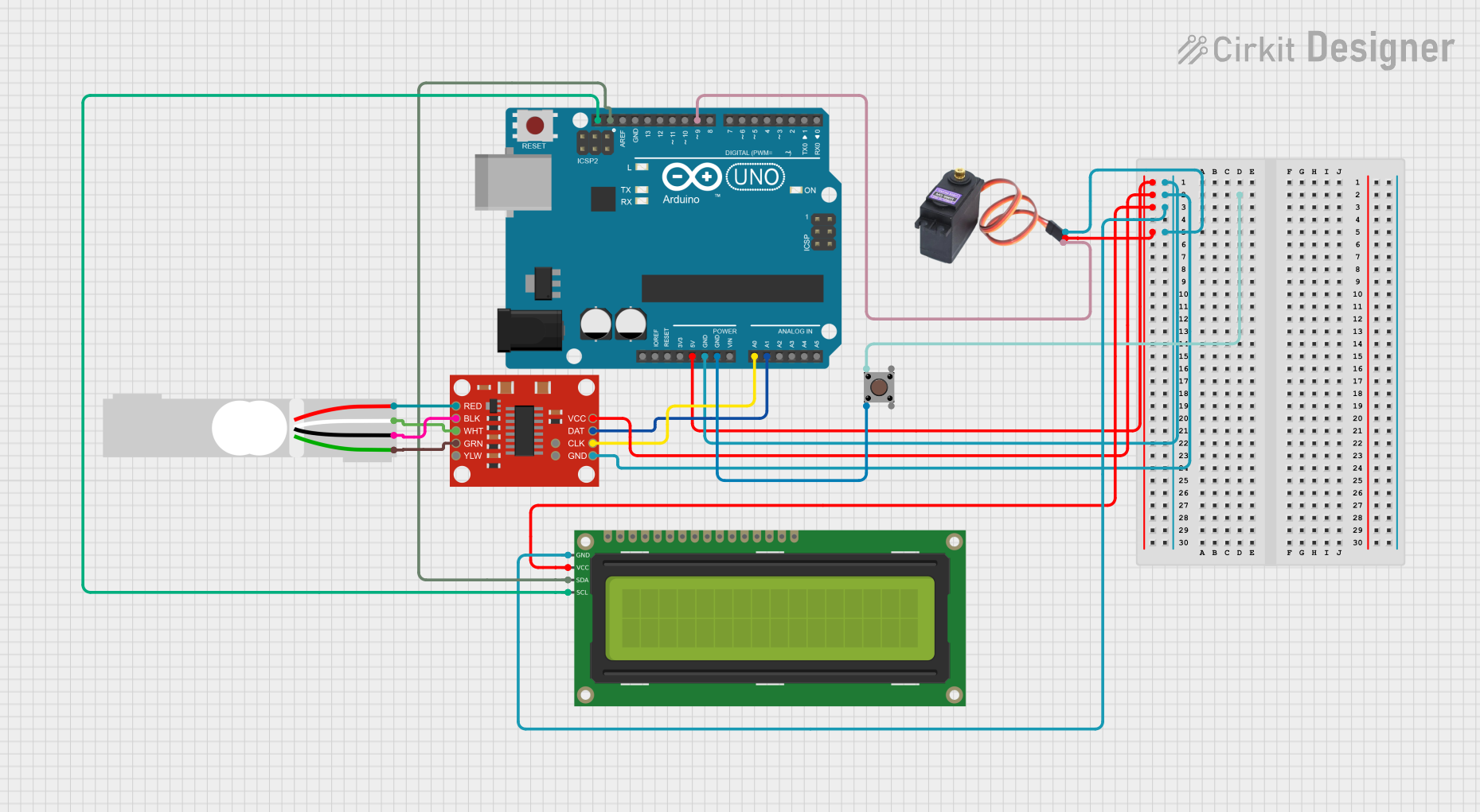
Explore Projects Built with Load Cell 500g
Technical Specifications
The Load Cell 500g is a strain gauge-based sensor that provides an analog output proportional to the applied force. Below are its key technical details:
General Specifications
- Maximum Load Capacity: 500 grams
- Rated Output: 1 mV/V (typical)
- Excitation Voltage: 5V DC (recommended), up to 10V DC (maximum)
- Output Impedance: ~350Ω
- Input Impedance: ~350Ω
- Non-linearity: ±0.03% of full scale
- Hysteresis: ±0.03% of full scale
- Operating Temperature Range: -10°C to +40°C
- Material: Aluminum alloy
- Dimensions: 34mm x 12mm x 12mm (approx.)
Pin Configuration and Descriptions
The Load Cell 500g typically has four wires for connection. The table below describes each wire:
| Wire Color | Function | Description |
|---|---|---|
| Red | Excitation+ (VCC) | Connect to the positive terminal of the excitation voltage (e.g., 5V). |
| Black | Excitation- (GND) | Connect to the ground terminal of the excitation voltage. |
| White | Signal+ (Output+) | Provides the positive side of the differential output signal. |
| Green | Signal- (Output-) | Provides the negative side of the differential output signal. |
Note: The output signal is very small (in millivolts) and typically requires an amplifier, such as the HX711 module, for proper interfacing with microcontrollers.
Usage Instructions
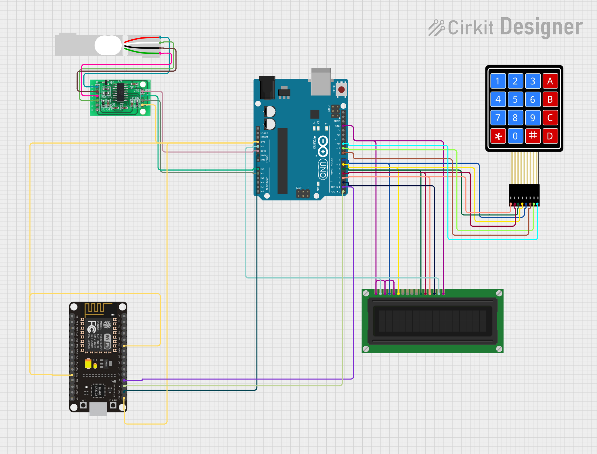
How to Use the Load Cell 500g in a Circuit
Connect the Load Cell to an Amplifier:
- Due to the small output signal, connect the load cell to an amplifier module like the HX711. The HX711 amplifies the signal and converts it to a digital format for easy interfacing with microcontrollers.
Wiring the Load Cell to the HX711:
- Connect the load cell wires to the HX711 module as follows:
- Red wire to E+ (Excitation+)
- Black wire to E- (Excitation-)
- White wire to A+ (Signal+)
- Green wire to A- (Signal-)
- Connect the HX711 module to your microcontroller (e.g., Arduino UNO) using the appropriate pins (e.g., DT and SCK).
- Connect the load cell wires to the HX711 module as follows:
Calibrate the Load Cell:
- Calibration is essential to ensure accurate weight measurements. Use known weights to determine the calibration factor for your setup.
Write Code for the Microcontroller:
- Below is an example Arduino code snippet for interfacing the Load Cell 500g with an HX711 module:
#include "HX711.h"

// Define HX711 pins
#define DT_PIN 3  // Data pin connected to HX711 DT
#define SCK_PIN 2 // Clock pin connected to HX711 SCK

HX711 scale;

void setup() {
  Serial.begin(9600); // Initialize serial communication
  scale.begin(DT_PIN, SCK_PIN); // Initialize HX711 with defined pins

  Serial.println("Calibrating... Place a known weight on the load cell.");
  delay(5000); // Wait for user to place a weight
  scale.set_scale(); // Set the scale to default calibration factor
  scale.tare(); // Reset the scale to zero
  Serial.println("Calibration complete.");
}

void loop() {
  // Read weight from the load cell
  float weight = scale.get_units(); // Get weight in grams
  Serial.print("Weight: ");
  Serial.print(weight);
  Serial.println(" g");

  delay(1000); // Wait 1 second before the next reading
}
Important Considerations and Best Practices
- Mounting: Ensure the load cell is securely mounted to avoid inaccurate readings due to vibrations or movement.
- Overloading: Do not exceed the 500g maximum load capacity, as this may damage the sensor.
- Temperature Effects: Use the load cell within the specified operating temperature range to maintain accuracy.
- Calibration: Always calibrate the load cell in your specific setup to account for environmental factors and mechanical tolerances.
Troubleshooting and FAQs
Common Issues and Solutions
No Output Signal:
- Cause: Incorrect wiring or no excitation voltage.
- Solution: Verify all connections and ensure the excitation voltage is applied.
Inaccurate Readings:
- Cause: Improper calibration or unstable mounting.
- Solution: Recalibrate the load cell and ensure it is securely mounted.
Fluctuating Measurements:
- Cause: Electrical noise or unstable power supply.
- Solution: Use a stable power source and add decoupling capacitors to reduce noise.
Output Stuck at Zero:
- Cause: Load cell damaged or HX711 module not functioning.
- Solution: Test the load cell with a multimeter to check resistance values. Replace if necessary.
FAQs
Q1: Can I use the Load Cell 500g without an amplifier?
A1: No, the output signal is too small to be read directly by most microcontrollers. An amplifier like the HX711 is required.
Q2: How do I determine the calibration factor?
A2: Use a known weight, measure the raw output, and calculate the factor by dividing the raw value by the weight.
Q3: Can I measure weights above 500g?
A3: No, exceeding the maximum capacity may permanently damage the load cell.
Q4: Is the Load Cell 500g waterproof?
A4: No, it is not waterproof. Avoid exposing it to moisture or liquids.
By following this documentation, you can effectively integrate the Load Cell 500g into your projects for accurate weight and force measurements.