Cirkit Designer Logo
Cirkit Designer
Your all-in-one circuit design IDE
Home / 
Component Documentation

How to Use Solar Isol: Examples, Pinouts, and Specs

Image of Solar Isol
Cirkit Designer LogoDesign with Solar Isol in Cirkit Designer

Introduction

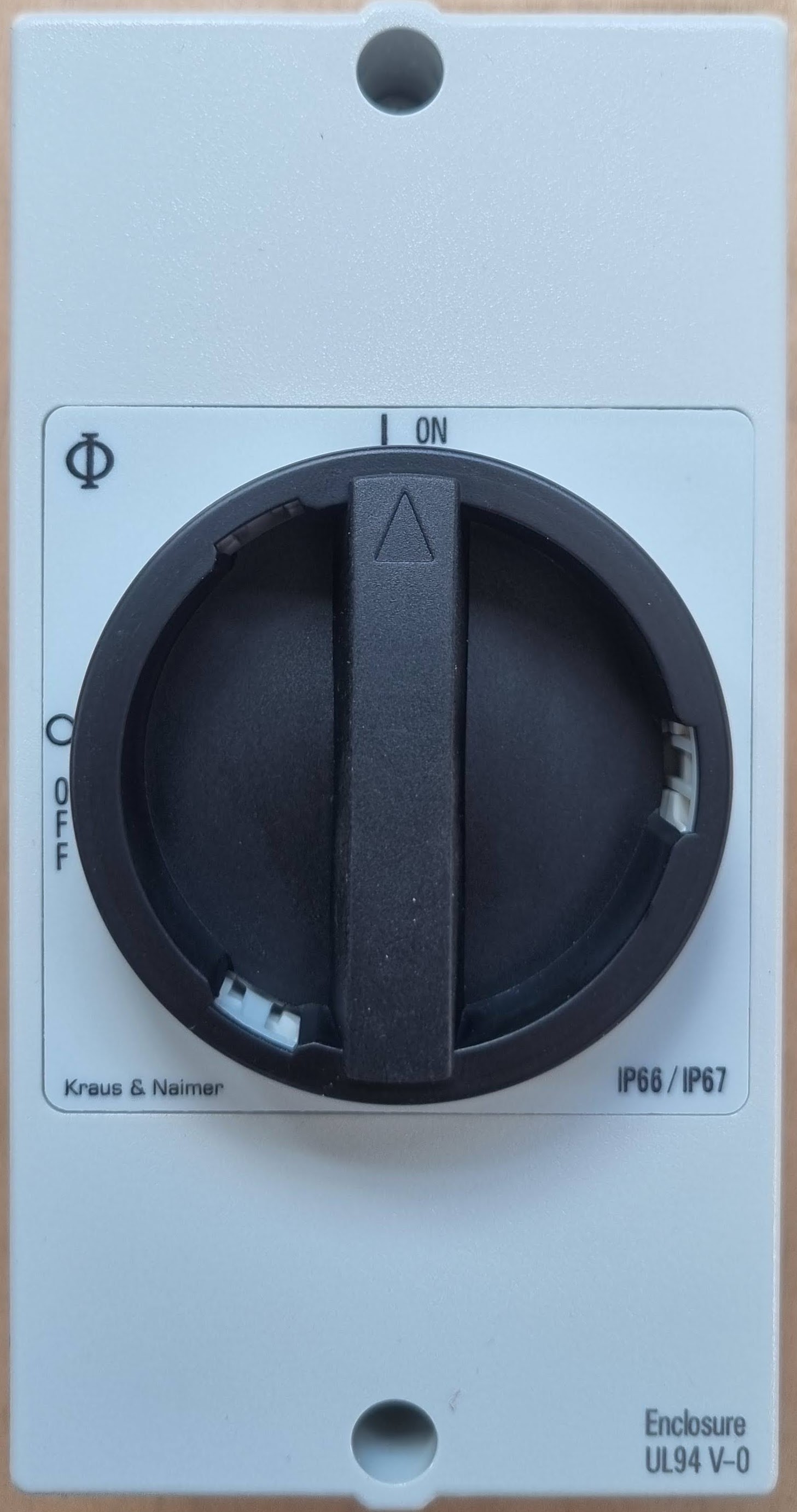
A Solar Isolator, commonly referred to as a solar disconnect switch, is a critical safety device in any photovoltaic (PV) system. It allows for the solar panel array to be isolated from the electrical system, ensuring that maintenance or emergency services can be performed safely without the risk of electric shock or damage to the system. Solar Isolators are typically installed in both the DC side, between the solar panels and the inverter, and the AC side, between the inverter and the grid connection.

Explore Projects Built with Solar Isol

Use Cirkit Designer to design, explore, and prototype these projects online. Some projects support real-time simulation. Click "Open Project" to start designing instantly!
Solar-Powered Battery Charging System with XL6009 Voltage Regulator
Image of SISTEMA DE ALIMENTACION Y CARGA SENSORES DS18B20 Y SENSOR DE TURBIDEZ: A project utilizing Solar Isol in a practical application
This circuit features a solar panel ('Do solara') connected to a voltage regulator ('XL6009 Voltage Regulator') to stabilize the output voltage. The regulated voltage is available at a terminal block ('Terminal PCB 2 Pin') for further use. Additionally, a Li-ion battery ('18650 Li-ion Battery') is connected to the solar panel for charging, with the solar panel's output also routed through the voltage regulator.
Cirkit Designer LogoOpen Project in Cirkit Designer
Solar-Powered Battery Backup System with Automatic Transfer Switch
Image of POWER SUPPLY: A project utilizing Solar Isol in a practical application
This circuit is a solar power management system that integrates a solar panel, battery, and inverter to provide a stable 12V DC and 220V AC output. It includes automatic transfer switches (ATS) and circuit breakers for safety and reliability, as well as a low voltage disconnect to protect the battery from deep discharge.
Cirkit Designer LogoOpen Project in Cirkit Designer
Solar-Powered Battery Backup System with ATS and 120V AC Outlet
Image of solar: A project utilizing Solar Isol in a practical application
This circuit is designed to convert solar energy into usable AC power for standard 120V appliances. It consists of a solar panel connected to a charge controller, which manages power flow to a 12V battery and an inverter. The inverter then converts the stored DC power from the battery into AC power, which is supplied to a 120V outlet through an Automatic Transfer Switch (ATS).
Cirkit Designer LogoOpen Project in Cirkit Designer
Solar-Powered Home Energy System with Automatic Transfer Switch and Battery Backup
Image of CDP: A project utilizing Solar Isol in a practical application
This circuit is a solar power system with an automatic transfer switch (ATS) that manages power from both a solar panel and an AC supply. The solar panel charges a battery through a solar charge controller, and the power inverter converts the stored DC power to AC, which is then distributed through an MCB to a socket. The ATS ensures seamless switching between solar and AC power sources.
Cirkit Designer LogoOpen Project in Cirkit Designer

Explore Projects Built with Solar Isol

Use Cirkit Designer to design, explore, and prototype these projects online. Some projects support real-time simulation. Click "Open Project" to start designing instantly!
Image of SISTEMA DE ALIMENTACION Y CARGA SENSORES DS18B20 Y SENSOR DE TURBIDEZ: A project utilizing Solar Isol in a practical application
Solar-Powered Battery Charging System with XL6009 Voltage Regulator
This circuit features a solar panel ('Do solara') connected to a voltage regulator ('XL6009 Voltage Regulator') to stabilize the output voltage. The regulated voltage is available at a terminal block ('Terminal PCB 2 Pin') for further use. Additionally, a Li-ion battery ('18650 Li-ion Battery') is connected to the solar panel for charging, with the solar panel's output also routed through the voltage regulator.
Cirkit Designer LogoOpen Project in Cirkit Designer
Image of POWER SUPPLY: A project utilizing Solar Isol in a practical application
Solar-Powered Battery Backup System with Automatic Transfer Switch
This circuit is a solar power management system that integrates a solar panel, battery, and inverter to provide a stable 12V DC and 220V AC output. It includes automatic transfer switches (ATS) and circuit breakers for safety and reliability, as well as a low voltage disconnect to protect the battery from deep discharge.
Cirkit Designer LogoOpen Project in Cirkit Designer
Image of solar: A project utilizing Solar Isol in a practical application
Solar-Powered Battery Backup System with ATS and 120V AC Outlet
This circuit is designed to convert solar energy into usable AC power for standard 120V appliances. It consists of a solar panel connected to a charge controller, which manages power flow to a 12V battery and an inverter. The inverter then converts the stored DC power from the battery into AC power, which is supplied to a 120V outlet through an Automatic Transfer Switch (ATS).
Cirkit Designer LogoOpen Project in Cirkit Designer
Image of CDP: A project utilizing Solar Isol in a practical application
Solar-Powered Home Energy System with Automatic Transfer Switch and Battery Backup
This circuit is a solar power system with an automatic transfer switch (ATS) that manages power from both a solar panel and an AC supply. The solar panel charges a battery through a solar charge controller, and the power inverter converts the stored DC power to AC, which is then distributed through an MCB to a socket. The ATS ensures seamless switching between solar and AC power sources.
Cirkit Designer LogoOpen Project in Cirkit Designer

Common Applications and Use Cases

  • Residential and commercial solar panel installations
  • Off-grid solar power systems
  • Grid-tied solar power systems with battery backup
  • Maintenance and repair of solar panel systems
  • Emergency shutdown of solar panel systems

Technical Specifications

Key Technical Details

  • Rated Voltage: The maximum DC voltage the isolator can handle.
  • Rated Current: The maximum current that can pass through the isolator.
  • Power Ratings: The maximum power capacity of the isolator.
  • Temperature Range: The operating temperature range of the isolator.
  • Enclosure Rating: The environmental protection provided by the isolator's enclosure.

Pin Configuration and Descriptions

Pin Number Description Notes
1 DC Positive Input From solar panels
2 DC Negative Input From solar panels
3 DC Positive Output To inverter or load
4 DC Negative Output To inverter or load
5 Grounding Terminal Safety ground connection

Usage Instructions

How to Use the Component in a Circuit

  1. Installation: The Solar Isolator should be installed by a qualified electrician, following local electrical codes and standards.
  2. Wiring: Connect the DC positive and negative inputs from the solar panels to the respective input terminals of the Solar Isolator. Similarly, connect the output terminals to the inverter or load.
  3. Operation: To engage the Solar Isolator, switch it to the 'ON' position. To isolate the solar panels from the electrical system, switch it to the 'OFF' position.

Important Considerations and Best Practices

  • Ensure that the Solar Isolator's voltage and current ratings match or exceed the solar system's specifications.
  • Install the Solar Isolator in an easily accessible location for quick operation in case of an emergency.
  • Regularly inspect the Solar Isolator for any signs of damage or corrosion.
  • Test the Solar Isolator periodically to ensure proper operation.

Troubleshooting and FAQs

Common Issues Users Might Face

  • Isolator Does Not Engage: Check for any obstructions or damage to the switch mechanism.
  • Electrical Arcing: Ensure that the connections are tight and secure to prevent arcing.
  • System Not Powering On: Verify that the Solar Isolator is in the 'ON' position and that all connections are correct.

Solutions and Tips for Troubleshooting

  • If the isolator does not engage, inspect the mechanism for debris or damage and clean or replace as necessary.
  • For electrical arcing, turn off the system and tighten all connections. If arcing persists, consult a professional.
  • If the system is not powering on, double-check the Solar Isolator's position and review all wiring connections.

FAQs

Q: Can I install a Solar Isolator myself? A: It is recommended that a qualified electrician install the Solar Isolator to ensure compliance with electrical codes and safety standards.

Q: How often should I test the Solar Isolator? A: Test the Solar Isolator every 6 months to ensure it is functioning correctly.

Q: What should I do if my Solar Isolator is damaged? A: If the Solar Isolator is damaged, it should be replaced immediately to maintain the safety and integrity of the solar system.

Q: Is a Solar Isolator required by law? A: In many regions, a Solar Isolator is required by law for solar installations. Always check local regulations.

Q: Can the Solar Isolator be used for both AC and DC applications? A: Solar Isolators are typically designed for DC applications. For AC isolation, a separate AC disconnect switch should be used.


This documentation provides a comprehensive overview of the Solar Isolator component. For further assistance or information, consult the manufacturer's datasheet or contact a professional.