How to Use 817 Module 8 channel: Examples, Pinouts, and Specs
Introduction
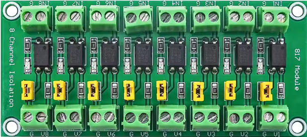
The 817 Module 8 Channel is a versatile signal processing unit designed to manage and route multiple audio or control signals across eight independent channels. This module is widely used in professional audio systems, automation systems, and other applications requiring efficient signal isolation and control. Its compact design and reliable performance make it a popular choice for both hobbyists and professionals.
Explore Projects Built with 817 Module 8 channel


Explore Projects Built with 817 Module 8 channel
Common Applications and Use Cases
- Audio signal routing in professional sound systems
- Signal isolation in automation and industrial control systems
- Multi-channel signal processing in home automation projects
- Integration with microcontrollers for signal control and monitoring
Technical Specifications
The 817 Module 8 Channel is built for robust performance and ease of integration. Below are its key technical specifications:
General Specifications
- Number of Channels: 8
- Input Voltage: 5V DC (logic side)
- Output Voltage: 3.3V to 24V DC (signal side)
- Maximum Current per Channel: 50mA
- Isolation Voltage: 5000V (optocoupler isolation)
- Operating Temperature: -40°C to 85°C
- Dimensions: 130mm x 50mm x 20mm
Pin Configuration and Descriptions
The module features an 8-channel input and output interface. Below is the pin configuration:
Input Side (Logic Control)
| Pin | Label | Description |
|---|---|---|
| 1 | IN1 | Input signal for Channel 1 |
| 2 | IN2 | Input signal for Channel 2 |
| 3 | IN3 | Input signal for Channel 3 |
| 4 | IN4 | Input signal for Channel 4 |
| 5 | IN5 | Input signal for Channel 5 |
| 6 | IN6 | Input signal for Channel 6 |
| 7 | IN7 | Input signal for Channel 7 |
| 8 | IN8 | Input signal for Channel 8 |
| 9 | VCC | 5V DC power supply for logic side |
| 10 | GND | Ground for logic side |
Output Side (Signal Control)
| Pin | Label | Description |
|---|---|---|
| 1 | OUT1 | Output signal for Channel 1 |
| 2 | OUT2 | Output signal for Channel 2 |
| 3 | OUT3 | Output signal for Channel 3 |
| 4 | OUT4 | Output signal for Channel 4 |
| 5 | OUT5 | Output signal for Channel 5 |
| 6 | OUT6 | Output signal for Channel 6 |
| 7 | OUT7 | Output signal for Channel 7 |
| 8 | OUT8 | Output signal for Channel 8 |
| 9 | V+ | External power supply for signal side |
| 10 | GND | Ground for signal side |
Usage Instructions
How to Use the 817 Module in a Circuit
- Power the Module: Connect the
VCCandGNDpins on the input side to a 5V DC power source. - Connect Input Signals: Attach the control signals (e.g., from a microcontroller) to the
IN1toIN8pins. - Connect Output Signals: Connect the devices or circuits to be controlled to the
OUT1toOUT8pins. - External Power for Outputs: Provide an appropriate external power supply to the
V+andGNDpins on the output side, matching the voltage requirements of the connected devices.
Important Considerations and Best Practices
- Ensure the input signals are within the logic voltage range (0-5V) to avoid damage.
- Use an external power supply for the output side if the connected devices require higher voltage or current.
- Avoid exceeding the maximum current rating of 50mA per channel.
- Use proper grounding to prevent noise or interference in the signals.
- For microcontroller integration, use pull-up or pull-down resistors if necessary to stabilize the input signals.
Example: Connecting to an Arduino UNO
Below is an example of how to control the 817 Module using an Arduino UNO:
Circuit Connections
- Connect the
VCCandGNDpins of the module to the 5V and GND pins of the Arduino. - Connect
IN1toIN8to digital pins 2 to 9 on the Arduino. - Connect the
V+andGNDpins on the output side to an external 12V power supply.
Arduino Code
// Define the input pins connected to the 817 Module
const int channelPins[8] = {2, 3, 4, 5, 6, 7, 8, 9};

void setup() {
  // Set all channel pins as outputs
  for (int i = 0; i < 8; i++) {
    pinMode(channelPins[i], OUTPUT);
    digitalWrite(channelPins[i], LOW); // Initialize all channels to OFF
  }
}

void loop() {
  // Example: Turn on each channel sequentially with a delay
  for (int i = 0; i < 8; i++) {
    digitalWrite(channelPins[i], HIGH); // Turn on the channel
    delay(500); // Wait for 500ms
    digitalWrite(channelPins[i], LOW); // Turn off the channel
  }
}
Troubleshooting and FAQs
Common Issues and Solutions
No Output Signal
- Cause: Missing or incorrect external power supply on the output side.
- Solution: Verify the
V+andGNDconnections and ensure the voltage matches the requirements of the connected devices.
Input Signals Not Responding
- Cause: Incorrect logic voltage levels or damaged input pins.
- Solution: Check the input signal voltage and ensure it is within the 0-5V range.
Interference or Noise in Signals
- Cause: Poor grounding or long signal wires.
- Solution: Use shorter wires and ensure proper grounding for both input and output sides.
Overheating
- Cause: Exceeding the maximum current rating of 50mA per channel.
- Solution: Reduce the load on the output channels or use external relays for high-current devices.
FAQs
Can I use the 817 Module with a 3.3V microcontroller? Yes, but ensure the input signals are compatible with the module's logic voltage range.
What is the purpose of the optocoupler isolation? The optocoupler provides electrical isolation between the input and output sides, protecting sensitive components from voltage spikes or noise.
Can I control AC devices with this module? No, the module is designed for DC signals only. Use external relays or solid-state switches for AC devices.