How to Use 1 Channel Relay 5V: Examples, Pinouts, and Specs
Introduction
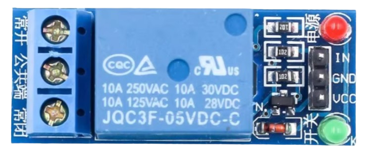
The 1 Channel Relay 5V is an electromechanical switching device that allows a low voltage control signal (e.g., from a microcontroller) to control a higher voltage circuit. This module is widely used in automation, home appliances, and industrial control systems to safely isolate and switch high-power devices such as lights, motors, and heaters.
Explore Projects Built with 1 Channel Relay 5V


Explore Projects Built with 1 Channel Relay 5V
Common Applications
- Home automation systems (e.g., controlling lights or fans)
- Industrial equipment control
- Motor and pump control
- IoT projects for remote switching
- Safety isolation between low voltage and high voltage circuits
Technical Specifications
The following table outlines the key technical details of the 1 Channel Relay 5V module:
| Parameter | Specification |
|---|---|
| Operating Voltage | 5V DC |
| Trigger Voltage | 3.3V to 5V DC |
| Maximum Load Voltage | 250V AC / 30V DC |
| Maximum Load Current | 10A |
| Relay Type | SPDT (Single Pole Double Throw) |
| Isolation | Optocoupler isolation for safety |
| Dimensions | ~50mm x 26mm x 18mm |
| Indicator LED | Yes (indicates relay activation) |
Pin Configuration
The 1 Channel Relay 5V module has the following pinout:
Input Pins (Low Voltage Side)
| Pin Name | Description |
|---|---|
| VCC | Connect to 5V DC power supply |
| GND | Connect to ground |
| IN | Control signal input (HIGH to activate relay) |
Output Terminals (High Voltage Side)
| Terminal Name | Description |
|---|---|
| COM | Common terminal for the load |
| NO | Normally Open terminal (connected to COM |
| when relay is activated) | |
| NC | Normally Closed terminal (connected to COM |
| when relay is deactivated) |
Usage Instructions
Connecting the Relay Module
- Power the Module: Connect the VCC pin to a 5V DC power source and the GND pin to ground.
- Control Signal: Connect the IN pin to a digital output pin of a microcontroller (e.g., Arduino UNO). When the IN pin receives a HIGH signal, the relay will activate.
- Load Connection:
- Connect the high voltage load to the COM terminal.
- Use the NO terminal if you want the load to be powered only when the relay is activated.
- Use the NC terminal if you want the load to be powered when the relay is deactivated.
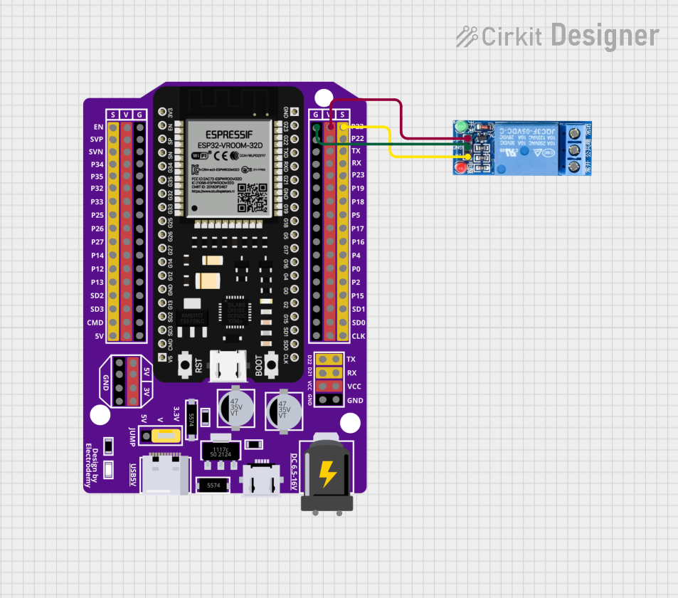
Example Circuit with Arduino UNO
Below is an example of how to connect and control the 1 Channel Relay 5V module using an Arduino UNO:
Circuit Diagram
- VCC: Connect to Arduino 5V pin.
- GND: Connect to Arduino GND pin.
- IN: Connect to Arduino digital pin 7.
Arduino Code
// Example code to control a 1 Channel Relay 5V module with Arduino UNO

#define RELAY_PIN 7  // Define the digital pin connected to the relay module

void setup() {
  pinMode(RELAY_PIN, OUTPUT);  // Set the relay pin as an output
  digitalWrite(RELAY_PIN, LOW);  // Ensure the relay is off at startup
}

void loop() {
  digitalWrite(RELAY_PIN, HIGH);  // Turn the relay ON
  delay(1000);  // Keep the relay ON for 1 second
  digitalWrite(RELAY_PIN, LOW);   // Turn the relay OFF
  delay(1000);  // Keep the relay OFF for 1 second
}
Important Considerations
- Power Supply: Ensure the module is powered with a stable 5V DC supply.
- Isolation: The relay provides electrical isolation between the control and load circuits. However, always handle high voltage connections with care.
- Load Ratings: Do not exceed the maximum voltage (250V AC / 30V DC) or current (10A) ratings of the relay.
- Flyback Diode: If controlling an inductive load (e.g., motor), use a flyback diode across the load to protect the relay from voltage spikes.
Troubleshooting and FAQs
Common Issues
Relay Not Activating:
- Check if the VCC and GND connections are secure.
- Ensure the control signal (IN pin) is receiving a HIGH signal (3.3V to 5V).
- Verify that the power supply provides sufficient current for the relay module.
Load Not Switching:
- Confirm that the load is properly connected to the COM and NO/NC terminals.
- Check if the load voltage and current are within the relay's rated limits.
Indicator LED Not Lighting Up:
- Ensure the module is powered correctly.
- Verify the control signal is functioning as expected.
FAQs
Q: Can I use this relay module with a 3.3V microcontroller?
A: Yes, the relay module can be triggered with a 3.3V control signal. However, ensure the VCC pin is still powered with 5V.
Q: Is the relay safe for switching high voltage AC loads?
A: Yes, the relay is designed for high voltage AC loads up to 250V. However, always follow proper safety precautions when working with high voltage.
Q: Can I control multiple relays with one Arduino?
A: Yes, you can control multiple relay modules by connecting each module's IN pin to a separate digital output pin on the Arduino.
Q: Why is the relay clicking but not switching the load?
A: This could be due to incorrect wiring on the high voltage side or a load that exceeds the relay's rated capacity. Double-check the connections and load specifications.
By following this documentation, you can effectively use the 1 Channel Relay 5V module in your projects for safe and reliable switching of high voltage circuits.