How to Use Coin Vibration Motor (large): Examples, Pinouts, and Specs
Introduction
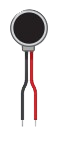
The large coin vibration motor is a compact electromechanical device designed to convert electrical energy into mechanical vibrations. It features a coin-shaped rotor with an unbalanced mass, which generates vibrations when the motor is powered. This component is widely used in applications requiring haptic feedback, such as mobile devices, gaming controllers, wearables, and medical devices. Its small size and ease of integration make it a popular choice for designers and engineers.
Explore Projects Built with Coin Vibration Motor (large)
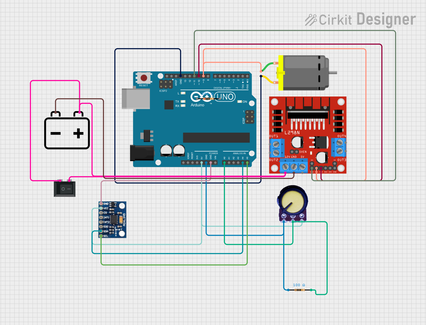

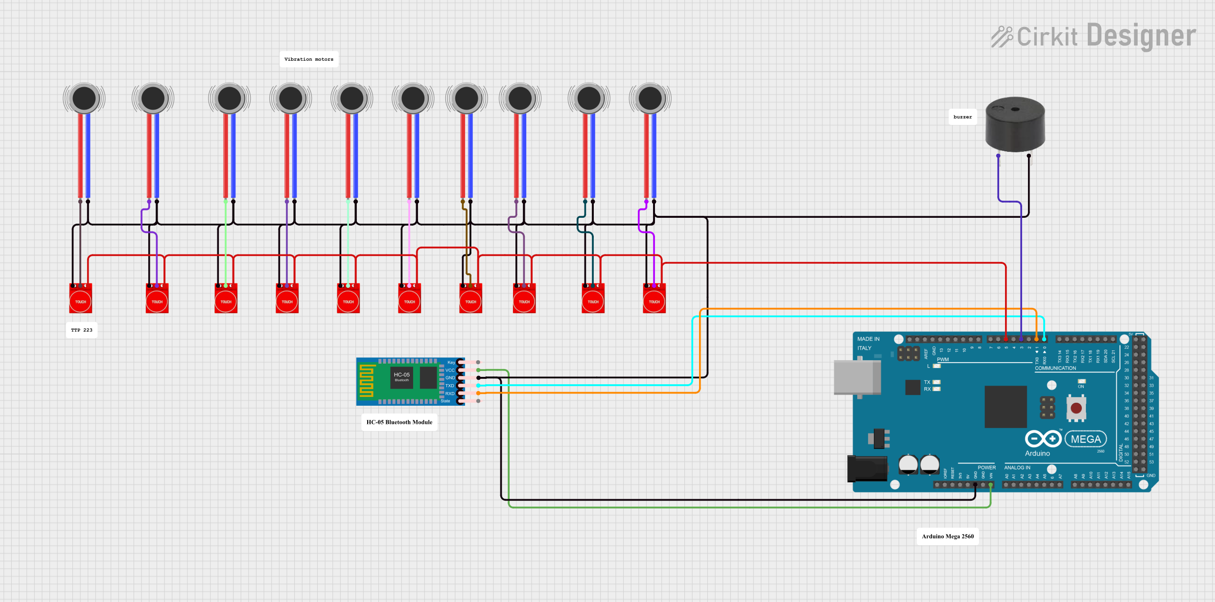

Explore Projects Built with Coin Vibration Motor (large)
Common Applications:
- Haptic feedback in mobile phones and gaming controllers
- Wearable devices for notifications and alerts
- Medical devices for tactile feedback
- Robotics and toys for vibration-based effects
Technical Specifications
Below are the key technical details for the large coin vibration motor:
| Parameter | Value |
|---|---|
| Operating Voltage | 2.5V to 3.7V |
| Rated Voltage | 3.0V |
| Operating Current | 80mA (typical at 3.0V) |
| Starting Voltage | 2.3V (minimum) |
| Vibration Amplitude | 1.0G (typical at 3.0V) |
| Motor Diameter | 10mm |
| Motor Thickness | 3.4mm |
| Operating Temperature | -20°C to +60°C |
| Connection Type | Wire leads |
Pin Configuration and Descriptions
The coin vibration motor typically has two wire leads for connection:
| Pin/Lead | Description |
|---|---|
| Red Lead | Positive terminal (+) for power |
| Black Lead | Negative terminal (-) for ground |
Usage Instructions
How to Use the Coin Vibration Motor in a Circuit
- Power Supply: Connect the red lead to a positive voltage source (2.5V to 3.7V) and the black lead to ground. Ensure the power supply matches the motor's rated voltage (3.0V) for optimal performance.
- Control with a Microcontroller: Use a transistor or MOSFET to control the motor with a microcontroller, as the motor's current draw (80mA) may exceed the microcontroller's output pin capacity.
- PWM Control: To adjust the vibration intensity, use Pulse Width Modulation (PWM) to vary the voltage supplied to the motor.
Circuit Example with Arduino UNO
Below is an example of how to connect and control the coin vibration motor using an Arduino UNO:
Circuit Diagram:
- Connect the red lead of the motor to the collector of an NPN transistor (e.g., 2N2222).
- Connect the black lead of the motor to the ground (GND).
- Connect the emitter of the transistor to GND.
- Connect a 1kΩ resistor between the Arduino digital pin (e.g., pin 9) and the base of the transistor.
- Connect the Arduino GND to the motor's GND.
Arduino Code Example:
// Coin Vibration Motor Control with Arduino UNO
// This code uses PWM to control the vibration intensity of the motor.

const int motorPin = 9; // Pin connected to the transistor base via a resistor

void setup() {
  pinMode(motorPin, OUTPUT); // Set motorPin as an output
}

void loop() {
  analogWrite(motorPin, 128); // Set motor to 50% intensity (PWM value: 128)
  delay(1000);                // Run motor for 1 second
  analogWrite(motorPin, 0);   // Turn off motor
  delay(1000);                // Wait for 1 second
}
Important Considerations and Best Practices
- Current Limiting: Ensure the power supply can handle the motor's current draw (80mA typical).
- Heat Management: Avoid prolonged operation at maximum voltage to prevent overheating.
- Mounting: Secure the motor firmly to prevent unwanted movement or noise during operation.
- Polarity: Always connect the red lead to the positive terminal and the black lead to ground to avoid damage.
Troubleshooting and FAQs
Common Issues and Solutions
| Issue | Possible Cause | Solution |
|---|---|---|
| Motor does not vibrate | Insufficient voltage or loose connections | Check power supply and ensure secure connections. |
| Weak or no vibration | Voltage below starting voltage (2.3V) | Increase the supply voltage to at least 2.5V. |
| Motor overheats | Prolonged operation at high voltage | Reduce operating voltage or limit runtime. |
| Noise or irregular vibration | Loose mounting or damaged motor | Secure the motor properly or replace it. |
FAQs
Can I power the motor directly from an Arduino pin?
- No, the motor's current draw (80mA) exceeds the Arduino's pin capacity. Use a transistor or MOSFET for control.
How can I adjust the vibration intensity?
- Use PWM to vary the voltage supplied to the motor. This can be done with a microcontroller like Arduino.
What happens if I reverse the polarity?
- Reversing the polarity may damage the motor. Always connect the red lead to the positive terminal and the black lead to ground.
Can I use this motor in battery-powered applications?
- Yes, the motor is suitable for battery-powered devices, but ensure the battery can supply sufficient current.
By following this documentation, you can effectively integrate and use the large coin vibration motor in your projects.