How to Use Duinotech 1.3" OLED Screen SPI: Examples, Pinouts, and Specs
Introduction
The Duinotech 1.3" OLED Screen SPI is a compact and versatile display module designed for embedded systems. Featuring a 1.3-inch OLED screen with a resolution of 128x64 pixels, this module provides crisp and clear visuals for text, graphics, and animations. It uses the SPI (Serial Peripheral Interface) communication protocol, ensuring fast and reliable data transfer between the display and microcontrollers.
This OLED screen is ideal for a wide range of applications, including:
- DIY electronics projects
- IoT devices
- Wearable technology
- Data visualization for sensors
- Compact user interfaces for embedded systems
Explore Projects Built with Duinotech 1.3" OLED Screen SPI


Explore Projects Built with Duinotech 1.3" OLED Screen SPI
Technical Specifications
Below are the key technical details of the Duinotech 1.3" OLED Screen SPI:
| Specification | Details |
|---|---|
| Display Type | OLED |
| Screen Size | 1.3 inches |
| Resolution | 128x64 pixels |
| Communication Protocol | SPI |
| Operating Voltage | 3.3V to 5V |
| Current Consumption | ~20mA (typical) |
| Driver IC | SSD1306 |
| Viewing Angle | >160° |
| Operating Temperature | -40°C to 85°C |
| Dimensions | 35mm x 35mm x 4mm |
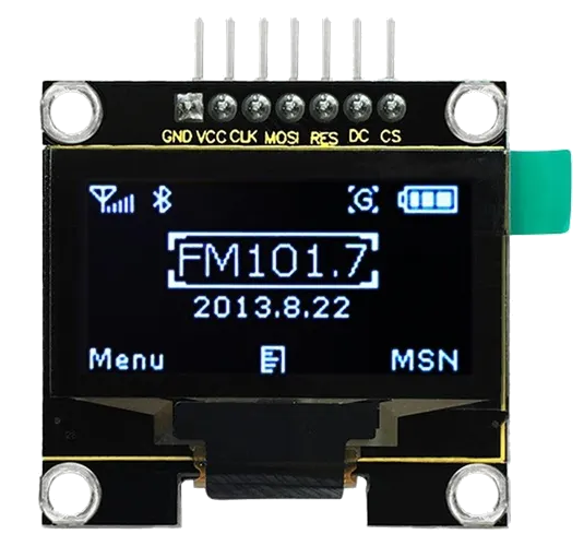
Pin Configuration and Descriptions
The Duinotech 1.3" OLED Screen SPI has a 7-pin interface. Below is the pinout and description:
| Pin | Name | Description |
|---|---|---|
| 1 | GND | Ground connection |
| 2 | VCC | Power supply (3.3V to 5V) |
| 3 | SCL | Serial Clock Line (SPI clock input) |
| 4 | SDA | Serial Data Line (SPI data input) |
| 5 | RES | Reset pin (active low) |
| 6 | DC | Data/Command control pin |
| 7 | CS | Chip Select (active low, used to enable the display) |
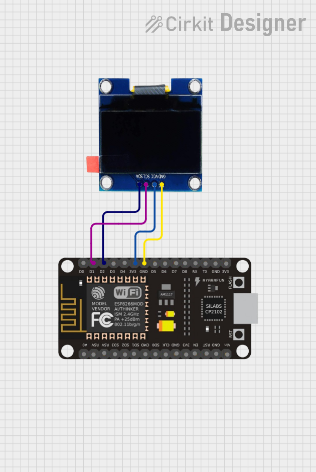
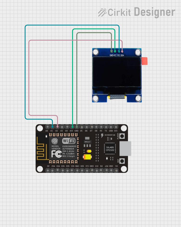
Usage Instructions
How to Use the Component in a Circuit
- Power Supply: Connect the
VCCpin to a 3.3V or 5V power source and theGNDpin to ground. - SPI Connections: Connect the
SCL(clock) andSDA(data) pins to the corresponding SPI pins on your microcontroller. - Control Pins:
- Connect the
RESpin to a GPIO pin on your microcontroller for resetting the display. - Connect the
DCpin to a GPIO pin to toggle between data and command modes. - Connect the
CSpin to a GPIO pin to enable or disable the display.
- Connect the
- Pull-Up Resistors: Ensure that the SPI lines have appropriate pull-up resistors if required by your microcontroller.
Important Considerations and Best Practices
- Voltage Compatibility: Ensure the microcontroller's logic level matches the display's voltage (3.3V or 5V).
- Reset Timing: Hold the
RESpin low for at least 10ms during initialization to reset the display. - SPI Speed: Use an SPI clock speed of up to 10MHz for optimal performance.
- Library Support: Use an SSD1306-compatible library for easier integration with microcontrollers like Arduino.
Example Code for Arduino UNO
Below is an example of how to use the Duinotech 1.3" OLED Screen SPI with an Arduino UNO. This code uses the popular Adafruit_SSD1306 library.
#include <Adafruit_GFX.h>       // Graphics library for OLED
#include <Adafruit_SSD1306.h>  // SSD1306 driver library

#define SCREEN_WIDTH 128        // OLED display width, in pixels
#define SCREEN_HEIGHT 64        // OLED display height, in pixels

// Declaration for SPI OLED display
#define OLED_MOSI   11          // Data pin (SDA)
#define OLED_CLK    13          // Clock pin (SCL)
#define OLED_DC     9           // Data/Command pin
#define OLED_CS     10          // Chip Select pin
#define OLED_RESET  8           // Reset pin

Adafruit_SSD1306 display(SCREEN_WIDTH, SCREEN_HEIGHT, &SPI, OLED_DC, OLED_RESET, OLED_CS);

void setup() {
  // Initialize the display
  if (!display.begin(SSD1306_SWITCHCAPVCC, 0x3C)) {
    // 0x3C is the I2C address; not used in SPI but required for library
    Serial.println(F("SSD1306 allocation failed"));
    for (;;); // Loop forever if initialization fails
  }

  display.clearDisplay();        // Clear the buffer
  display.setTextSize(1);        // Set text size to 1
  display.setTextColor(SSD1306_WHITE); // Set text color to white
  display.setCursor(0, 0);       // Set cursor to top-left corner
  display.println(F("Hello, Duinotech!")); // Print text
  display.display();             // Display the text
}

void loop() {
  // Add your code here for dynamic updates
}
Troubleshooting and FAQs
Common Issues and Solutions
Display Not Turning On:
- Verify the power supply connections (
VCCandGND). - Ensure the
CSpin is correctly connected and set low during communication.
- Verify the power supply connections (
No Output on the Screen:
- Check the SPI connections (
SCLandSDA) for loose or incorrect wiring. - Ensure the
RESpin is properly toggled during initialization.
- Check the SPI connections (
Flickering or Corrupted Display:
- Reduce the SPI clock speed to improve signal integrity.
- Check for noise or interference on the SPI lines.
Library Errors:
- Ensure the
Adafruit_SSD1306andAdafruit_GFXlibraries are installed in the Arduino IDE. - Verify that the correct pins are defined in the code.
- Ensure the
FAQs
Q: Can I use this display with a 3.3V microcontroller?
A: Yes, the display is compatible with both 3.3V and 5V logic levels.
Q: What is the maximum SPI clock speed supported?
A: The display supports SPI clock speeds of up to 10MHz.
Q: Can I use this display with I2C instead of SPI?
A: No, this specific model is designed for SPI communication only.
Q: How do I display custom graphics?
A: Use the Adafruit_GFX library to draw shapes, bitmaps, and other graphics on the screen.
Q: Is the display sunlight-readable?
A: While the OLED screen is bright, it may not be easily readable in direct sunlight.
By following this documentation, you can effectively integrate the Duinotech 1.3" OLED Screen SPI into your projects and troubleshoot common issues.