How to Use Charger + Boost Converter DD05CVSA: Examples, Pinouts, and Specs
Introduction
The DD05CVSA is a versatile electronic module that combines the functionalities of a battery charger and a boost converter. This dual-purpose component is designed to efficiently charge batteries while simultaneously stepping up the voltage to a desired level, making it an ideal choice for a wide range of electronic applications.
Explore Projects Built with Charger + Boost Converter DD05CVSA
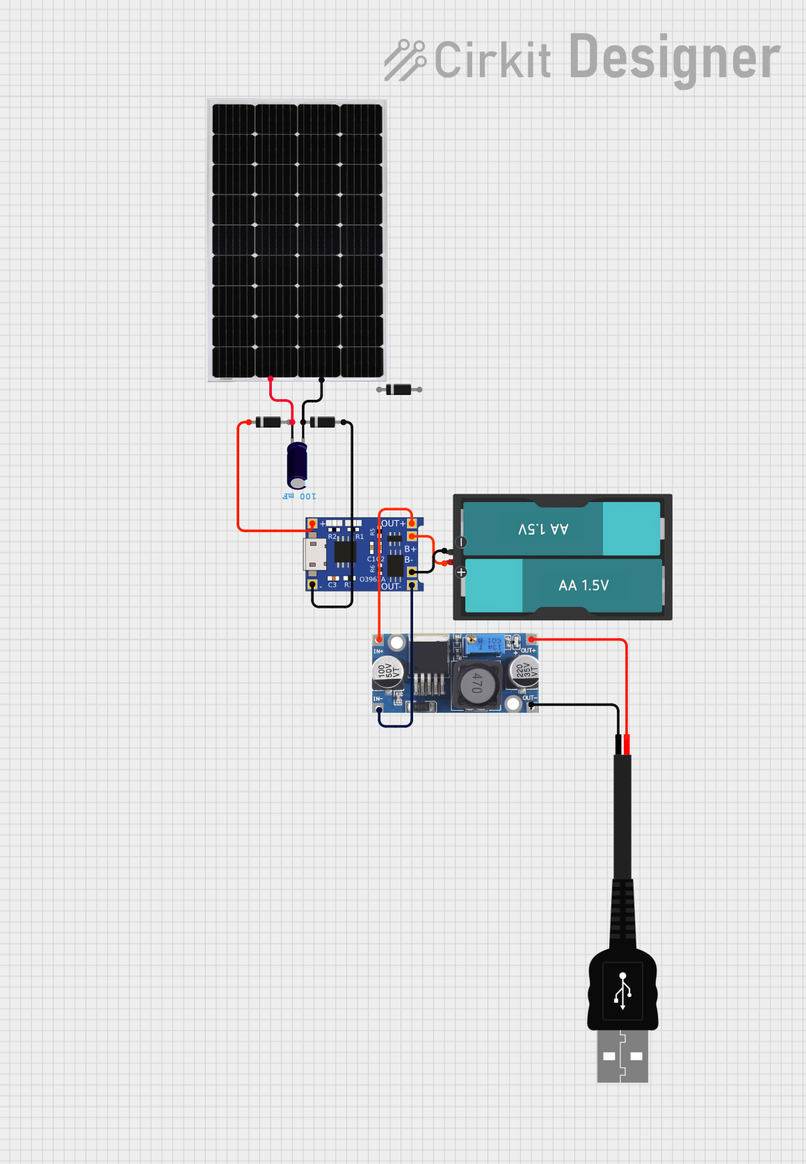


Explore Projects Built with Charger + Boost Converter DD05CVSA
Common Applications and Use Cases
- Portable Electronics: Powering and charging portable devices such as smartphones, tablets, and handheld gadgets.
- DIY Projects: Ideal for hobbyists and makers working on battery-powered projects.
- Renewable Energy Systems: Used in solar-powered systems to charge batteries and boost voltage for various applications.
- Emergency Power Supplies: Useful in creating backup power solutions where both charging and voltage regulation are required.
Technical Specifications
Key Technical Details
| Parameter | Value |
|---|---|
| Input Voltage Range | 3.5V - 12V |
| Output Voltage Range | 5V - 12V (adjustable) |
| Charging Current | 1A (max) |
| Output Current | 2A (max) |
| Efficiency | Up to 92% |
| Dimensions | 22mm x 17mm x 4mm |
| Operating Temperature | -40°C to 85°C |
Pin Configuration and Descriptions
| Pin Number | Pin Name | Description |
|---|---|---|
| 1 | IN+ | Positive input voltage |
| 2 | IN- | Negative input voltage (ground) |
| 3 | OUT+ | Positive output voltage |
| 4 | OUT- | Negative output voltage (ground) |
| 5 | BAT+ | Positive battery terminal |
| 6 | BAT- | Negative battery terminal (ground) |
| 7 | ADJ | Voltage adjustment pin (for setting output voltage) |
Usage Instructions
How to Use the Component in a Circuit
Connecting the Input:
- Connect the positive input voltage to the
IN+pin. - Connect the negative input voltage (ground) to the
IN-pin.
- Connect the positive input voltage to the
Connecting the Output:
- Connect the positive output voltage to the
OUT+pin. - Connect the negative output voltage (ground) to the
OUT-pin.
- Connect the positive output voltage to the
Connecting the Battery:
- Connect the positive battery terminal to the
BAT+pin. - Connect the negative battery terminal (ground) to the
BAT-pin.
- Connect the positive battery terminal to the
Adjusting the Output Voltage:
- Use a small screwdriver to turn the potentiometer connected to the
ADJpin. - Measure the output voltage with a multimeter and adjust until the desired voltage is reached.
- Use a small screwdriver to turn the potentiometer connected to the
Important Considerations and Best Practices
- Heat Dissipation: Ensure adequate ventilation or heat sinking to prevent overheating, especially when operating at high currents.
- Polarity: Double-check the polarity of all connections to avoid damaging the module.
- Voltage Limits: Do not exceed the specified input and output voltage ranges to ensure safe operation.
- Battery Compatibility: Ensure the battery type and specifications are compatible with the charging current and voltage of the module.
Troubleshooting and FAQs
Common Issues and Solutions
No Output Voltage:
- Solution: Check all connections for proper polarity and secure attachment. Ensure the input voltage is within the specified range.
Overheating:
- Solution: Reduce the load current or improve heat dissipation by adding a heatsink or increasing airflow around the module.
Inconsistent Output Voltage:
- Solution: Verify the stability of the input voltage. Adjust the potentiometer carefully and ensure it is not loose.
FAQs
Q: Can I use this module to charge any type of battery? A: The module is designed for lithium-ion and lithium-polymer batteries. Ensure the battery specifications match the module's charging current and voltage.
Q: How do I set the output voltage?
A: Use a small screwdriver to adjust the potentiometer connected to the ADJ pin while monitoring the output voltage with a multimeter.
Q: Is it safe to use this module in outdoor projects? A: The module can operate in a wide temperature range, but ensure it is protected from moisture and extreme environmental conditions.
Example Code for Arduino UNO
If you are using the DD05CVSA module with an Arduino UNO, you can monitor the battery voltage and control the output voltage using the following example code:
// Example code to monitor battery voltage and control output voltage
// using Arduino UNO and DD05CVSA module

const int batteryPin = A0; // Analog pin to read battery voltage
const int outputPin = 9;   // PWM pin to control output voltage

void setup() {
  Serial.begin(9600); // Initialize serial communication
  pinMode(outputPin, OUTPUT); // Set output pin as output
}

void loop() {
  int batteryValue = analogRead(batteryPin); // Read battery voltage
  float batteryVoltage = batteryValue * (5.0 / 1023.0) * 2; // Convert to voltage

  Serial.print("Battery Voltage: ");
  Serial.print(batteryVoltage);
  Serial.println(" V");

  // Control output voltage (example: set to 50% duty cycle)
  analogWrite(outputPin, 128); // 50% duty cycle (0-255 range)

  delay(1000); // Wait for 1 second
}
This code reads the battery voltage using an analog pin and controls the output voltage using a PWM pin. Adjust the analogWrite value to change the duty cycle and control the output voltage accordingly.
By following this documentation, users can effectively utilize the Charger + Boost Converter DD05CVSA module in their electronic projects, ensuring efficient charging and voltage regulation.