Cirkit Designer
Your all-in-one circuit design IDE
Home /
Component Documentation
How to Use raspberry pi pico w: Examples, Pinouts, and Specs
Introduction
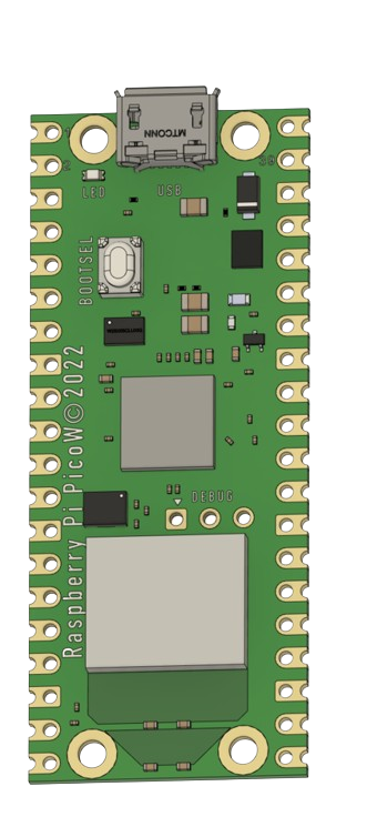
The Raspberry Pi Pico W is a highly versatile microcontroller board designed by Raspberry Pi, featuring the RP2040 microcontroller chip. It is an extension of the original Raspberry Pi Pico, with the added functionality of wireless connectivity. The Pico W supports both Bluetooth and Wi-Fi, making it an excellent choice for Internet of Things (IoT) projects, wireless sensor networks, and smart home applications.
Explore Projects Built with raspberry pi pico w
Wi-Fi Controlled RGB Lighting with Raspberry Pi Pico W
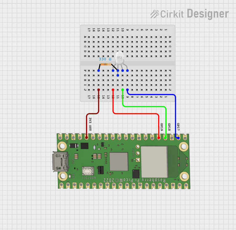
This circuit features a Raspberry Pi Pico W microcontroller connected to an RGB LED through GPIO pins GP17, GP18, and GP19 for controlling the blue, green, and red channels, respectively. A resistor is connected between the 3V3 OUT pin of the Pico and the common cathode of the RGB LED to limit the current. The embedded code suggests the Pico W is configured for Wi-Fi connectivity and MQTT communication to control the LED and possibly other peripherals not shown in the circuit, with additional functionality for sensor monitoring and display output.
Raspberry Pi Pico W-Based Smart Home Automation System with Motion Detection and Environmental Monitoring
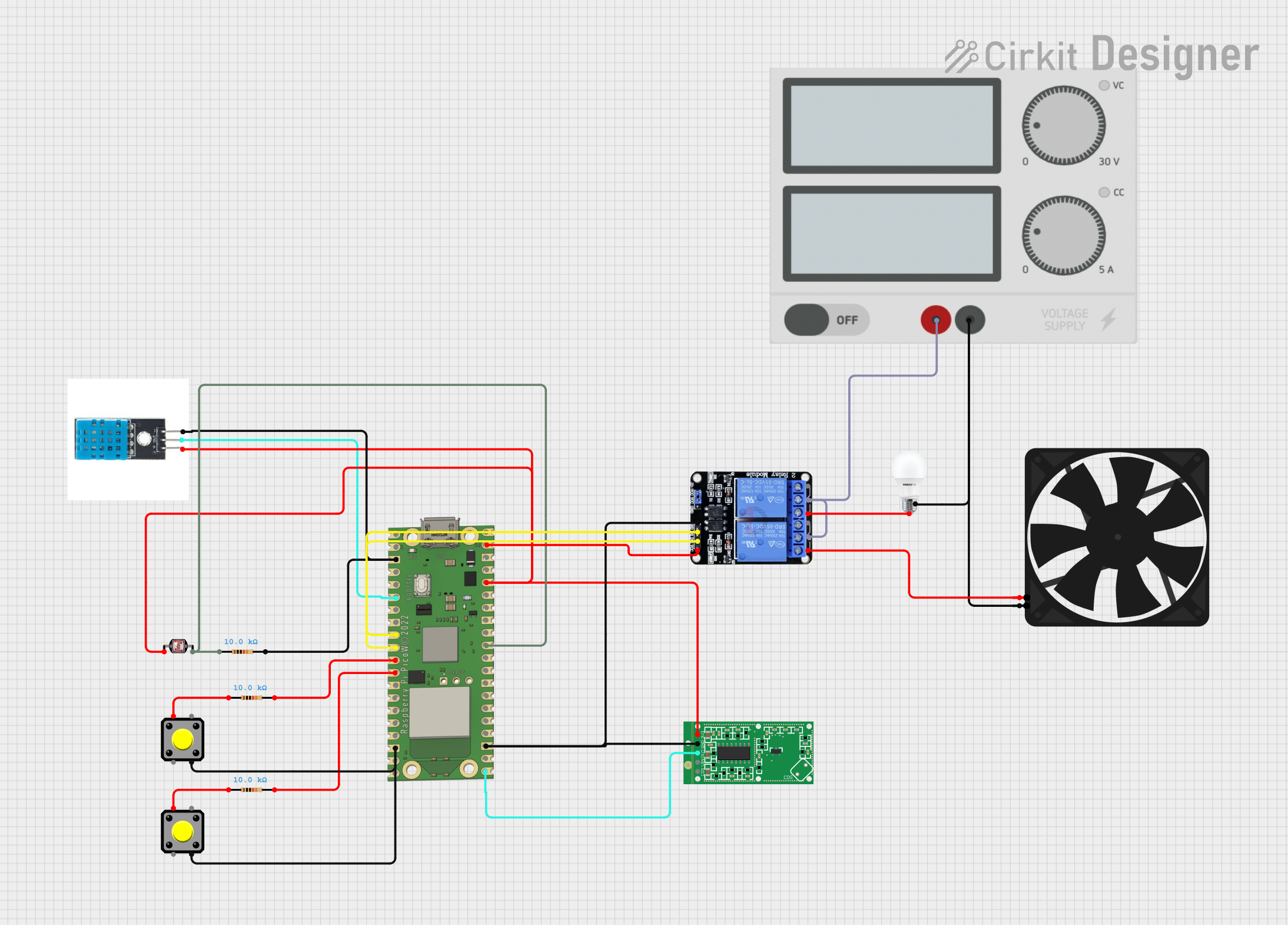
This circuit features a Raspberry Pi Pico W microcontroller connected to various sensors and actuators, including a DHT11 temperature and humidity sensor, an RCWL-0516 microwave radar motion sensor, a photocell (LDR) with a resistor for light detection, and a two-channel relay controlling a bulb and a fan. The microcontroller runs code to monitor environmental conditions and motion, displaying information on an LCD and allowing remote control via MQTT messages over Wi-Fi. It supports both automatic sensor-based operation and remote app control, with pushbuttons to switch between modes.
Raspberry Pi Pico W RGB LED Controller with Resistors
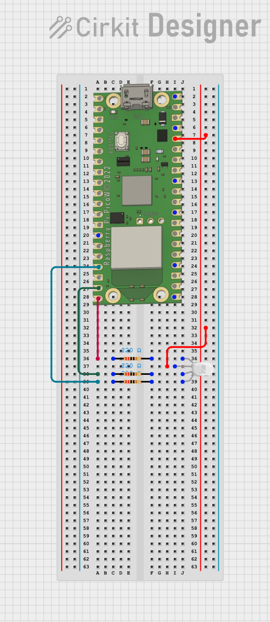
This circuit uses a Raspberry Pi Pico W to control an RGB LED through three 220-ohm resistors connected to its GPIO pins. The Pico W provides 3.3V power to the common anode of the RGB LED, allowing for color control via the GPIO pins GP13, GP14, and GP15.
Raspberry Pi Pico and ESP32 Wi-Fi Controlled Sensor Interface

This circuit integrates a Raspberry Pi Pico and an ESP32 Wroom Dev Kit, interconnected through various GPIO pins and resistors, to enable communication and control between the two microcontrollers. The ESP32 is powered by a 3.3V supply and shares ground with the Raspberry Pi Pico, while specific GPIO pins are used for data exchange. The provided code sketches for the Raspberry Pi Pico suggest a framework for further development of the system's functionality.
Explore Projects Built with raspberry pi pico w
Wi-Fi Controlled RGB Lighting with Raspberry Pi Pico W
This circuit features a Raspberry Pi Pico W microcontroller connected to an RGB LED through GPIO pins GP17, GP18, and GP19 for controlling the blue, green, and red channels, respectively. A resistor is connected between the 3V3 OUT pin of the Pico and the common cathode of the RGB LED to limit the current. The embedded code suggests the Pico W is configured for Wi-Fi connectivity and MQTT communication to control the LED and possibly other peripherals not shown in the circuit, with additional functionality for sensor monitoring and display output.
Raspberry Pi Pico W-Based Smart Home Automation System with Motion Detection and Environmental Monitoring
This circuit features a Raspberry Pi Pico W microcontroller connected to various sensors and actuators, including a DHT11 temperature and humidity sensor, an RCWL-0516 microwave radar motion sensor, a photocell (LDR) with a resistor for light detection, and a two-channel relay controlling a bulb and a fan. The microcontroller runs code to monitor environmental conditions and motion, displaying information on an LCD and allowing remote control via MQTT messages over Wi-Fi. It supports both automatic sensor-based operation and remote app control, with pushbuttons to switch between modes.
Raspberry Pi Pico W RGB LED Controller with Resistors
This circuit uses a Raspberry Pi Pico W to control an RGB LED through three 220-ohm resistors connected to its GPIO pins. The Pico W provides 3.3V power to the common anode of the RGB LED, allowing for color control via the GPIO pins GP13, GP14, and GP15.
Raspberry Pi Pico and ESP32 Wi-Fi Controlled Sensor Interface
This circuit integrates a Raspberry Pi Pico and an ESP32 Wroom Dev Kit, interconnected through various GPIO pins and resistors, to enable communication and control between the two microcontrollers. The ESP32 is powered by a 3.3V supply and shares ground with the Raspberry Pi Pico, while specific GPIO pins are used for data exchange. The provided code sketches for the Raspberry Pi Pico suggest a framework for further development of the system's functionality.
Technical Specifications
Key Technical Details
- Microcontroller: RP2040 by Raspberry Pi
- Wireless Connectivity: 2.4 GHz 802.11n Wi-Fi and Bluetooth 4.2 / BLE
- CPU: Dual-core ARM Cortex-M0+ processor, up to 133 MHz
- Memory: 264KB of SRAM, and 2MB of on-board Flash memory
- GPIO Pins: 26 multi-function GPIO pins
- Interfaces: 2 × UART, 2 × SPI, 2 × I2C, 3 × 12-bit ADC, 16 × controllable PWM channels
- Input Voltage: 1.8–5.5V DC
- Operating Temperature: -20°C to +85°C
Pin Configuration and Descriptions
| Pin Number | Name | Description |
|---|---|---|
| 1-20 | GP0-GP19 | General Purpose I/O pins |
| 21 | RUN | Reset pin, active low |
| 22-24 | GND | Ground pins |
| 25-26 | 3V3_EN, VSYS | Power pins |
| 27-36 | GP20-GP29 | General Purpose I/O pins |
| 37-40 | AGND, 3V3(OUT), VBUS, VREF | Analog ground, output voltage, USB input voltage, ADC reference voltage |
Usage Instructions
Integrating with a Circuit
To use the Raspberry Pi Pico W in a circuit:
- Powering the Pico W: Connect a power source to the VSYS pin and a ground connection to one of the GND pins. The Pico W can be powered via USB or an external battery.
- Connecting I/O: Utilize the GPIO pins for interfacing with sensors, actuators, and other peripherals. Ensure that the voltage levels are compatible with the Pico W's 3.3V logic.
- Programming: Use the micro-USB port to connect the Pico W to a computer for programming. The board can be programmed using C/C++ SDK or MicroPython.
Best Practices
- Always ensure that the power supply is within the specified range to prevent damage.
- Use proper decoupling capacitors close to the power pins to minimize power supply noise.
- Avoid exposing the board to temperatures outside the specified operating range.
- When using Wi-Fi or Bluetooth, consider the placement of the Pico W to ensure optimal signal strength and minimal interference.
Troubleshooting and FAQs
Common Issues
- Wi-Fi or Bluetooth not connecting: Ensure that the antenna area is not obstructed and that the correct credentials and protocols are being used.
- Program not running: Check the power supply and connections. Ensure that the code has been uploaded correctly.
- Unexpected behavior in peripherals: Verify that the GPIO pins are configured correctly and that there are no shorts or incorrect connections in the circuit.
Solutions and Tips
- Wi-Fi/Bluetooth troubleshooting: Restart the Pico W and check the wireless settings in your code. Ensure that the firmware is up to date.
- Code upload issues: Try a different USB cable or port. Make sure that the BOOTSEL button is pressed when connecting the Pico W to enter bootloader mode.
- Peripheral issues: Use pull-up or pull-down resistors as needed for stable readings. Check the datasheets of connected components for proper interfacing.
Example Code for Arduino UNO Connectivity
// This example demonstrates how to toggle an LED on the Pico W
// using a digital output from an Arduino UNO.

#include <Wire.h>

// Define the I2C address for Pico W (adjust as needed)
#define PICO_W_I2C_ADDR 0x61

void setup() {
  Wire.begin(); // Start I2C as master
  pinMode(LED_BUILTIN, OUTPUT); // Initialize the built-in LED
}

void loop() {
  Wire.beginTransmission(PICO_W_I2C_ADDR); // Start transmission to Pico W
  Wire.write(HIGH); // Send a HIGH signal
  Wire.endTransmission(); // End transmission

  digitalWrite(LED_BUILTIN, HIGH); // Turn on the LED on UNO
  delay(1000); // Wait for 1 second

  Wire.beginTransmission(PICO_W_I2C_ADDR); // Start transmission to Pico W
  Wire.write(LOW); // Send a LOW signal
  Wire.endTransmission(); // End transmission

  digitalWrite(LED_BUILTIN, LOW); // Turn off the LED on UNO
  delay(1000); // Wait for 1 second
}
Note: This code assumes that the Raspberry Pi Pico W has been set up to communicate via I2C and respond to the signals sent by the Arduino UNO. The actual implementation on the Pico W side would need to be programmed to handle the I2C communication appropriately.