Cirkit Designer Logo
Cirkit Designer
Your all-in-one circuit design IDE
Home / 
Component Documentation

How to Use PCA9865: Examples, Pinouts, and Specs

Image of PCA9865
Cirkit Designer LogoDesign with PCA9865 in Cirkit Designer

Introduction

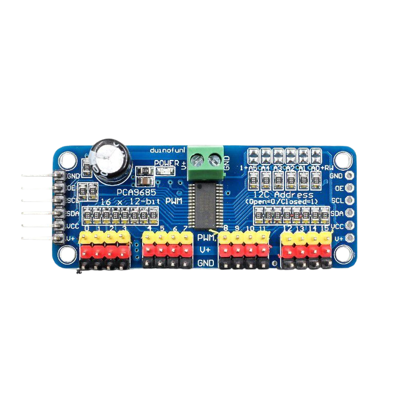
The PCA9685 is a 16-channel I2C bus LED driver with an integrated PWM (Pulse Width Modulation) controller. Manufactured by NXP Semiconductors, this component is designed to provide precise control of LED brightness and color mixing. It is widely used in applications such as LED displays, RGB lighting systems, robotics (e.g., servo motor control), and other projects requiring multiple PWM outputs.

The PCA9685 simplifies the process of controlling multiple LEDs or servos by offloading the PWM generation from the microcontroller, freeing up resources for other tasks. It supports a wide range of operating voltages and is compatible with popular microcontrollers like Arduino, Raspberry Pi, and others.

Explore Projects Built with PCA9865

Use Cirkit Designer to design, explore, and prototype these projects online. Some projects support real-time simulation. Click "Open Project" to start designing instantly!
Battery-Powered Raspberry Pi Pico GPS Tracker with Sensor Integration
Image of Copy of CanSet v1: A project utilizing PCA9865 in a practical application
This circuit is a data acquisition and communication system powered by a LiPoly battery and managed by a Raspberry Pi Pico. It includes sensors (BMP280, MPU9250) for environmental data, a GPS module for location tracking, an SD card for data storage, and a WLR089-CanSAT for wireless communication. The TP4056 module handles battery charging, and a toggle switch controls power distribution.
Cirkit Designer LogoOpen Project in Cirkit Designer
Raspberry Pi Pico-Based Navigation Assistant with Bluetooth and GPS
Image of sat_dish: compass example: A project utilizing PCA9865 in a practical application
This circuit features a Raspberry Pi Pico microcontroller interfaced with an HC-05 Bluetooth module for wireless communication, an HMC5883L compass module for magnetic field measurement, and a GPS NEO 6M module for location tracking. The Pico is configured to communicate with the HC-05 via serial connection (TX/RX), with the compass module via I2C (SCL/SDA), and with the GPS module via serial (TX/RX). Common power (VCC) and ground (GND) lines are shared among all modules, indicating a unified power system.
Cirkit Designer LogoOpen Project in Cirkit Designer
Raspberry Pi Pico-Based Bluetooth Compass
Image of sat_dish: compass-intro: A project utilizing PCA9865 in a practical application
This circuit features a Raspberry Pi Pico microcontroller interfaced with an HC-05 Bluetooth module and an HMC5883L digital compass. The Pico's GPIO pins are configured for serial communication with the HC-05 (TX/RX) and I2C communication with the HMC5883L (SCL/SDA). The circuit is likely designed for wireless data transmission of compass readings.
Cirkit Designer LogoOpen Project in Cirkit Designer
Arduino Mega 2560 Based Security System with Fingerprint Authentication and SMS Alerts
Image of Door security system: A project utilizing PCA9865 in a practical application
This circuit features an Arduino Mega 2560 microcontroller interfaced with a SIM800L GSM module, two fingerprint scanners, an I2C LCD display, an IR sensor, and a piezo buzzer. Power management is handled by a PowerBoost 1000 Basic Pad USB, a TP4056 charging module, and a Li-ion 18650 battery, with an option to use a Mini AC-DC 110V-230V to 5V 700mA module for direct power supply. The primary functionality appears to be a security system with GSM communication capabilities, biometric access control, and visual/audible feedback.
Cirkit Designer LogoOpen Project in Cirkit Designer

Explore Projects Built with PCA9865

Use Cirkit Designer to design, explore, and prototype these projects online. Some projects support real-time simulation. Click "Open Project" to start designing instantly!
Image of Copy of CanSet v1: A project utilizing PCA9865 in a practical application
Battery-Powered Raspberry Pi Pico GPS Tracker with Sensor Integration
This circuit is a data acquisition and communication system powered by a LiPoly battery and managed by a Raspberry Pi Pico. It includes sensors (BMP280, MPU9250) for environmental data, a GPS module for location tracking, an SD card for data storage, and a WLR089-CanSAT for wireless communication. The TP4056 module handles battery charging, and a toggle switch controls power distribution.
Cirkit Designer LogoOpen Project in Cirkit Designer
Image of sat_dish: compass example: A project utilizing PCA9865 in a practical application
Raspberry Pi Pico-Based Navigation Assistant with Bluetooth and GPS
This circuit features a Raspberry Pi Pico microcontroller interfaced with an HC-05 Bluetooth module for wireless communication, an HMC5883L compass module for magnetic field measurement, and a GPS NEO 6M module for location tracking. The Pico is configured to communicate with the HC-05 via serial connection (TX/RX), with the compass module via I2C (SCL/SDA), and with the GPS module via serial (TX/RX). Common power (VCC) and ground (GND) lines are shared among all modules, indicating a unified power system.
Cirkit Designer LogoOpen Project in Cirkit Designer
Image of sat_dish: compass-intro: A project utilizing PCA9865 in a practical application
Raspberry Pi Pico-Based Bluetooth Compass
This circuit features a Raspberry Pi Pico microcontroller interfaced with an HC-05 Bluetooth module and an HMC5883L digital compass. The Pico's GPIO pins are configured for serial communication with the HC-05 (TX/RX) and I2C communication with the HMC5883L (SCL/SDA). The circuit is likely designed for wireless data transmission of compass readings.
Cirkit Designer LogoOpen Project in Cirkit Designer
Image of Door security system: A project utilizing PCA9865 in a practical application
Arduino Mega 2560 Based Security System with Fingerprint Authentication and SMS Alerts
This circuit features an Arduino Mega 2560 microcontroller interfaced with a SIM800L GSM module, two fingerprint scanners, an I2C LCD display, an IR sensor, and a piezo buzzer. Power management is handled by a PowerBoost 1000 Basic Pad USB, a TP4056 charging module, and a Li-ion 18650 battery, with an option to use a Mini AC-DC 110V-230V to 5V 700mA module for direct power supply. The primary functionality appears to be a security system with GSM communication capabilities, biometric access control, and visual/audible feedback.
Cirkit Designer LogoOpen Project in Cirkit Designer

Technical Specifications

The PCA9685 has the following key technical specifications:

  • Operating Voltage (Vcc): 2.3V to 5.5V
  • Logic Voltage Levels: Compatible with 3.3V and 5V logic
  • PWM Resolution: 12-bit (4096 steps)
  • Number of Channels: 16 independent PWM outputs
  • PWM Frequency Range: Adjustable from 24 Hz to 1526 Hz
  • I2C Address Range: Configurable via 6 address pins (up to 62 devices on the same bus)
  • Maximum Output Current per Channel: 25 mA (sink) or 10 mA (source)
  • Operating Temperature Range: -40°C to +85°C
  • Package Type: TSSOP-28

Pin Configuration and Descriptions

The PCA9685 comes in a 28-pin TSSOP package. Below is the pin configuration:

Pin Number Pin Name Description
1 LED0 PWM output for channel 0
2 LED1 PWM output for channel 1
3-16 LED2-LED15 PWM outputs for channels 2 to 15
17 VCC Power supply input (2.3V to 5.5V)
18 GND Ground
19 SDA I2C data line
20 SCL I2C clock line
21-26 A0-A5 I2C address selection pins (used to set the device's I2C address)
27 OE Output enable (active low, disables all outputs when high)
28 EXTCLK External clock input (optional, for custom PWM frequency)

Usage Instructions

How to Use the PCA9685 in a Circuit

  1. Power Supply:

    • Connect the VCC pin to a 3.3V or 5V power source, depending on your system.
    • Connect the GND pin to the ground of your circuit.
  2. I2C Communication:

    • Connect the SDA and SCL pins to the corresponding I2C pins on your microcontroller.
    • Use pull-up resistors (typically 4.7kΩ) on the SDA and SCL lines if not already present.
  3. Address Configuration:

    • Use the A0-A5 pins to set the I2C address of the PCA9685. Each pin can be connected to VCC (logic high) or GND (logic low) to configure the address.
  4. PWM Outputs:

    • Connect LEDs, servos, or other devices to the LED0-LED15 pins. Ensure that the current draw does not exceed the maximum ratings.
  5. External Clock (Optional):

    • If a custom PWM frequency is required, connect an external clock signal to the EXTCLK pin.

Example: Using PCA9685 with Arduino UNO

Below is an example of how to control the PCA9685 using an Arduino UNO to dim an LED connected to channel 0.

Circuit Connections

  • Connect VCC to the Arduino's 5V pin.
  • Connect GND to the Arduino's GND pin.
  • Connect SDA to the Arduino's A4 pin.
  • Connect SCL to the Arduino's A5 pin.
  • Connect an LED (with a current-limiting resistor) to the LED0 pin.

Arduino Code

#include <Wire.h>
#include <Adafruit_PWMServoDriver.h>

// Create an instance of the PCA9685 driver
Adafruit_PWMServoDriver pwm = Adafruit_PWMServoDriver();

void setup() {
  // Initialize I2C communication
  Wire.begin();
  
  // Initialize the PCA9685 with the default I2C address (0x40)
  pwm.begin();
  
  // Set the PWM frequency to 1000 Hz
  pwm.setPWMFreq(1000);
}

void loop() {
  // Gradually increase brightness on channel 0
  for (int i = 0; i < 4096; i++) {
    pwm.setPWM(0, 0, i); // Set PWM value for channel 0
    delay(1);            // Small delay for smooth dimming
  }

  // Gradually decrease brightness on channel 0
  for (int i = 4095; i >= 0; i--) {
    pwm.setPWM(0, 0, i); // Set PWM value for channel 0
    delay(1);            // Small delay for smooth dimming
  }
}

Important Considerations and Best Practices

  • Power Supply: Ensure that the power supply can handle the total current draw of all connected devices.
  • I2C Pull-Up Resistors: Verify that pull-up resistors are present on the SDA and SCL lines to ensure reliable communication.
  • PWM Frequency: Choose an appropriate PWM frequency for your application. For servos, a frequency of 50 Hz is typical.
  • Output Enable (OE): Use the OE pin to disable all outputs when needed (e.g., during system initialization).

Troubleshooting and FAQs

Common Issues

  1. No Response from PCA9685:

    • Check the I2C connections (SDA, SCL) and ensure pull-up resistors are present.
    • Verify the I2C address configuration (A0-A5 pins).
  2. LEDs Not Lighting Up:

    • Ensure the LEDs are connected with the correct polarity.
    • Check the current-limiting resistors and ensure they are appropriate for the LEDs.
  3. PWM Output is Erratic:

    • Verify that the power supply is stable and sufficient for the load.
    • Check for noise or interference on the I2C lines.

FAQs

Q: Can the PCA9685 control servos?
A: Yes, the PCA9685 is commonly used to control servos. Set the PWM frequency to 50 Hz and adjust the duty cycle to control the servo position.

Q: How many PCA9685 modules can I connect to a single I2C bus?
A: Up to 62 PCA9685 modules can be connected to a single I2C bus by configuring the A0-A5 address pins.

Q: Can I use an external clock with the PCA9685?
A: Yes, you can connect an external clock signal to the EXTCLK pin to set a custom PWM frequency.

Q: Is the PCA9685 compatible with 3.3V microcontrollers?
A: Yes, the PCA9685 is compatible with both 3.3V and 5V logic levels.