Cirkit Designer Logo
Cirkit Designer
Your all-in-one circuit design IDE
Home / 
Component Documentation

How to Use OPA818 w/Breakout: Examples, Pinouts, and Specs

Image of OPA818 w/Breakout
Cirkit Designer LogoDesign with OPA818 w/Breakout in Cirkit Designer

Introduction

The OPA818 w/Breakout is a high-performance operational amplifier (op-amp) from Texas Instruments (TI), designed for a wide range of analog signal processing tasks. This op-amp is known for its high bandwidth, low noise, and fast slew rate, making it ideal for applications such as high-speed data acquisition, active filters, and photodiode amplification. The breakout board simplifies the integration of the OPA818 into various circuits by providing easy access to the op-amp's pins through standard headers.

Explore Projects Built with OPA818 w/Breakout

Use Cirkit Designer to design, explore, and prototype these projects online. Some projects support real-time simulation. Click "Open Project" to start designing instantly!
Battery-Powered Force Sensing System with nRF52840 and OPA688P
Image of BCT-BLE-Sensor: A project utilizing OPA818 w/Breakout in a practical application
This circuit is a sensor interface system that uses a Seeed Studio nRF52840 microcontroller to process signals from a force sensing resistor and a rotary potentiometer. The OPA688P operational amplifier conditions the sensor signals, which are then read by the microcontroller for further processing or transmission.
Cirkit Designer LogoOpen Project in Cirkit Designer
ESP32-C3 Mini and MCP4725 DAC Controlled Analog Output Circuit
Image of pp: A project utilizing OPA818 w/Breakout in a practical application
This circuit features an ESP32-C3 Mini microcontroller that interfaces with an Adafruit MCP4725 DAC via I2C for analog output, which is then fed into an OPA2333 operational amplifier. Power management is handled by a 5V step-down voltage regulator that receives power from a 2000mAh battery and supplies the ESP32-C3 and a 3.3V AMS1117 voltage regulator. Additionally, the circuit includes user input through buttons and electro pads, with debouncing provided by resistors.
Cirkit Designer LogoOpen Project in Cirkit Designer
Battery-Powered Environmental Monitoring System with ESP32, BNO055, and MS5803-14BA
Image of bencana banjir: A project utilizing OPA818 w/Breakout in a practical application
This circuit is a sensor network powered by a LiPo battery through a step-down buck converter, which supplies power to multiple ESP32 microcontrollers, a BNO055 IMU, an ultrasonic sensor, and a pressure sensor. The ESP32 microcontrollers handle data acquisition from the sensors and are programmed to process and transmit this data. The sensors are connected to the ESP32s via I2C and GPIO pins for communication and data collection.
Cirkit Designer LogoOpen Project in Cirkit Designer
ESP32-Controlled OLED Display and Servo with DotStar LED Strip and Audio Output
Image of Arena 2: A project utilizing OPA818 w/Breakout in a practical application
This circuit features an ESP32 microcontroller driving a variety of components. It controls an OLED display for visual output, a DotStar LED strip for lighting effects, a PAM8403 audio amplifier connected to a speaker for sound output, and a PCA9685 PWM Servo Breakout to manage a servo motor. The ESP32 also interfaces with a piezo speaker for additional sound generation, and the circuit is powered by a 18650 Li-ion battery setup with a TP4056 charging module. The ESP32's embedded code handles the display animation on the OLED.
Cirkit Designer LogoOpen Project in Cirkit Designer

Explore Projects Built with OPA818 w/Breakout

Use Cirkit Designer to design, explore, and prototype these projects online. Some projects support real-time simulation. Click "Open Project" to start designing instantly!
Image of BCT-BLE-Sensor: A project utilizing OPA818 w/Breakout in a practical application
Battery-Powered Force Sensing System with nRF52840 and OPA688P
This circuit is a sensor interface system that uses a Seeed Studio nRF52840 microcontroller to process signals from a force sensing resistor and a rotary potentiometer. The OPA688P operational amplifier conditions the sensor signals, which are then read by the microcontroller for further processing or transmission.
Cirkit Designer LogoOpen Project in Cirkit Designer
Image of pp: A project utilizing OPA818 w/Breakout in a practical application
ESP32-C3 Mini and MCP4725 DAC Controlled Analog Output Circuit
This circuit features an ESP32-C3 Mini microcontroller that interfaces with an Adafruit MCP4725 DAC via I2C for analog output, which is then fed into an OPA2333 operational amplifier. Power management is handled by a 5V step-down voltage regulator that receives power from a 2000mAh battery and supplies the ESP32-C3 and a 3.3V AMS1117 voltage regulator. Additionally, the circuit includes user input through buttons and electro pads, with debouncing provided by resistors.
Cirkit Designer LogoOpen Project in Cirkit Designer
Image of bencana banjir: A project utilizing OPA818 w/Breakout in a practical application
Battery-Powered Environmental Monitoring System with ESP32, BNO055, and MS5803-14BA
This circuit is a sensor network powered by a LiPo battery through a step-down buck converter, which supplies power to multiple ESP32 microcontrollers, a BNO055 IMU, an ultrasonic sensor, and a pressure sensor. The ESP32 microcontrollers handle data acquisition from the sensors and are programmed to process and transmit this data. The sensors are connected to the ESP32s via I2C and GPIO pins for communication and data collection.
Cirkit Designer LogoOpen Project in Cirkit Designer
Image of Arena 2: A project utilizing OPA818 w/Breakout in a practical application
ESP32-Controlled OLED Display and Servo with DotStar LED Strip and Audio Output
This circuit features an ESP32 microcontroller driving a variety of components. It controls an OLED display for visual output, a DotStar LED strip for lighting effects, a PAM8403 audio amplifier connected to a speaker for sound output, and a PCA9685 PWM Servo Breakout to manage a servo motor. The ESP32 also interfaces with a piezo speaker for additional sound generation, and the circuit is powered by a 18650 Li-ion battery setup with a TP4056 charging module. The ESP32's embedded code handles the display animation on the OLED.
Cirkit Designer LogoOpen Project in Cirkit Designer

Common Applications and Use Cases

  • High-speed data acquisition systems
  • Active filters for signal processing
  • Photodiode amplifiers for optical detection
  • Audio amplifiers for high-fidelity sound systems
  • Medical instrumentation
  • Test and measurement equipment

Technical Specifications

Key Technical Details

  • Supply Voltage Range: ±2.25V to ±18V
  • Bandwidth: 1.8 GHz
  • Slew Rate: 4900 V/µs
  • Input Noise: 0.69 nV/√Hz
  • Output Current: 100 mA
  • Operating Temperature Range: -40°C to +125°C

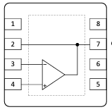
Pin Configuration and Descriptions

Pin Number Pin Name Description
1 VOUT Output voltage pin
2 V- Negative power supply input
3 VIN- Inverting input
4 VIN+ Non-inverting input
5 V+ Positive power supply input
6 NC No connection (reserved for future use)
7 NC No connection (reserved for future use)
8 NC No connection (reserved for future use)

Usage Instructions

How to Use the Component in a Circuit

  1. Power Supply Connections:

    • Connect the positive power supply to the V+ pin and the negative power supply to the V- pin. Ensure that the supply voltage is within the specified range.
  2. Input Signal:

    • Apply the signal to be amplified to the VIN+ pin for non-inverting configurations or to the VIN- pin for inverting configurations.
  3. Output:

    • Connect the VOUT pin to the next stage of your circuit or to the load.
  4. Feedback Network:

    • Connect a feedback network between the output and input pins to set the gain of the amplifier.
  5. Bypass Capacitors:

    • Place bypass capacitors close to the power supply pins to minimize noise and provide a stable operation.

Important Considerations and Best Practices

  • Always use a proper heat sink if the op-amp is expected to dissipate significant power.
  • Keep the input and output traces as short as possible to reduce parasitic capacitance and inductance.
  • Ensure that the power supply is clean and well-regulated.
  • Avoid running high-speed signal traces parallel to noisy lines to prevent coupling.
  • Use proper grounding techniques to minimize ground loops and noise.

Troubleshooting and FAQs

Common Issues Users Might Face

  • Oscillation: This can occur if the feedback network is not properly designed or if there is insufficient power supply decoupling.
  • Output Clipping: If the output voltage exceeds the power supply rails, the op-amp will clip the signal.
  • Excessive Noise: Poor layout, inadequate power supply filtering, or using the op-amp outside its specified bandwidth can introduce noise.

Solutions and Tips for Troubleshooting

  • Ensure that the feedback network is correctly designed for the desired gain and bandwidth.
  • Check that the power supply voltages are within the specified range and that bypass capacitors are in place.
  • Review the PCB layout to minimize the length of high-speed signal paths and to optimize the grounding scheme.

FAQs

Q: Can the OPA818 w/Breakout be used in single-supply configurations? A: Yes, but ensure that the input and output voltage ranges are within the limits of the single supply voltage.

Q: What is the maximum gain I can achieve with this op-amp? A: The maximum gain is limited by the bandwidth of the op-amp. Higher gains will reduce the bandwidth proportionally.

Q: How can I improve the stability of the op-amp in my circuit? A: Use proper decoupling techniques, ensure that the feedback network is designed for the intended application, and follow good PCB layout practices.

Example Code for Arduino UNO

// Example code for interfacing OPA818 w/Breakout with Arduino UNO
// This code assumes the op-amp is configured for a non-inverting amplifier

const int analogInputPin = A0; // Connect the output of the op-amp to A0
const int analogOutputPin = 9; // PWM output pin

void setup() {
  Serial.begin(9600);
}

void loop() {
  int sensorValue = analogRead(analogInputPin); // Read the amplified signal
  float voltage = sensorValue * (5.0 / 1023.0); // Convert to voltage
  Serial.println(voltage); // Print the voltage to the Serial Monitor
  delay(100); // Wait for 100 milliseconds
}

Note: The above code is a simple example to read the amplified signal from the OPA818 w/Breakout and print the voltage to the Serial Monitor. The actual implementation will depend on the specific application and circuit configuration.