
How to Use SparkFun PWM Shield: Examples, Pinouts, and Specs
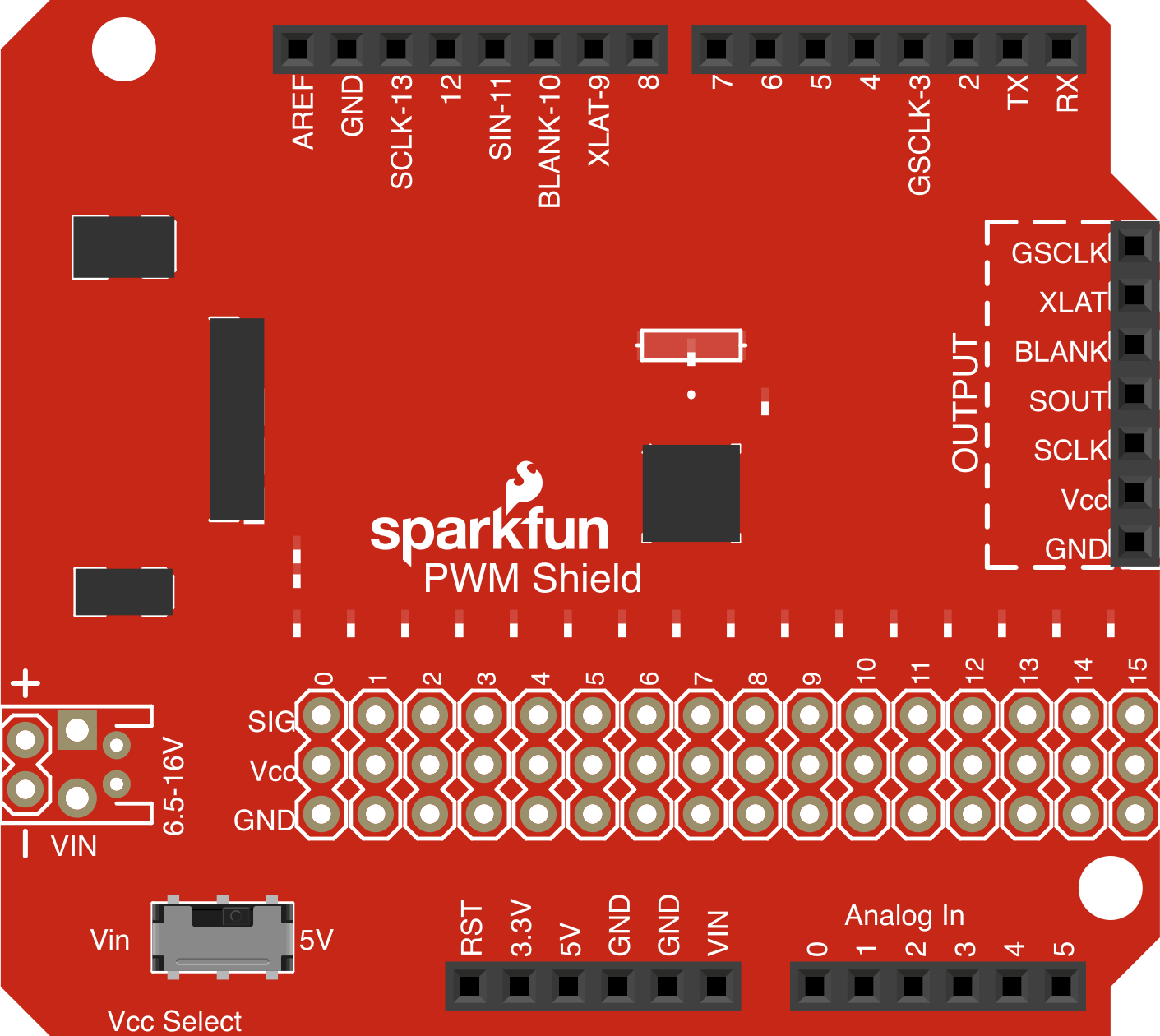
 Design with SparkFun PWM Shield in Cirkit Designer
Introduction
The SparkFun PWM Shield (DEV-10615) is a versatile add-on board designed for Arduino platforms. It provides multiple Pulse Width Modulation (PWM) outputs, enabling precise control of devices such as servos, motors, LEDs, and other components requiring variable speed, brightness, or position. This shield simplifies the process of generating PWM signals, making it ideal for robotics, automation, and lighting projects.
Explore Projects Built with SparkFun PWM Shield
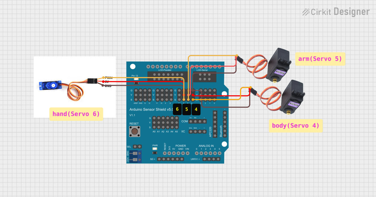 Open Project in Cirkit Designer
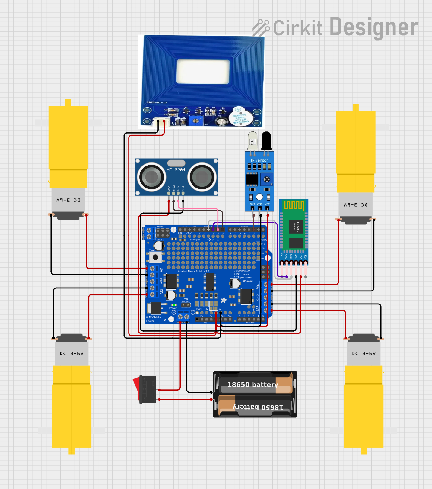 Open Project in Cirkit Designer
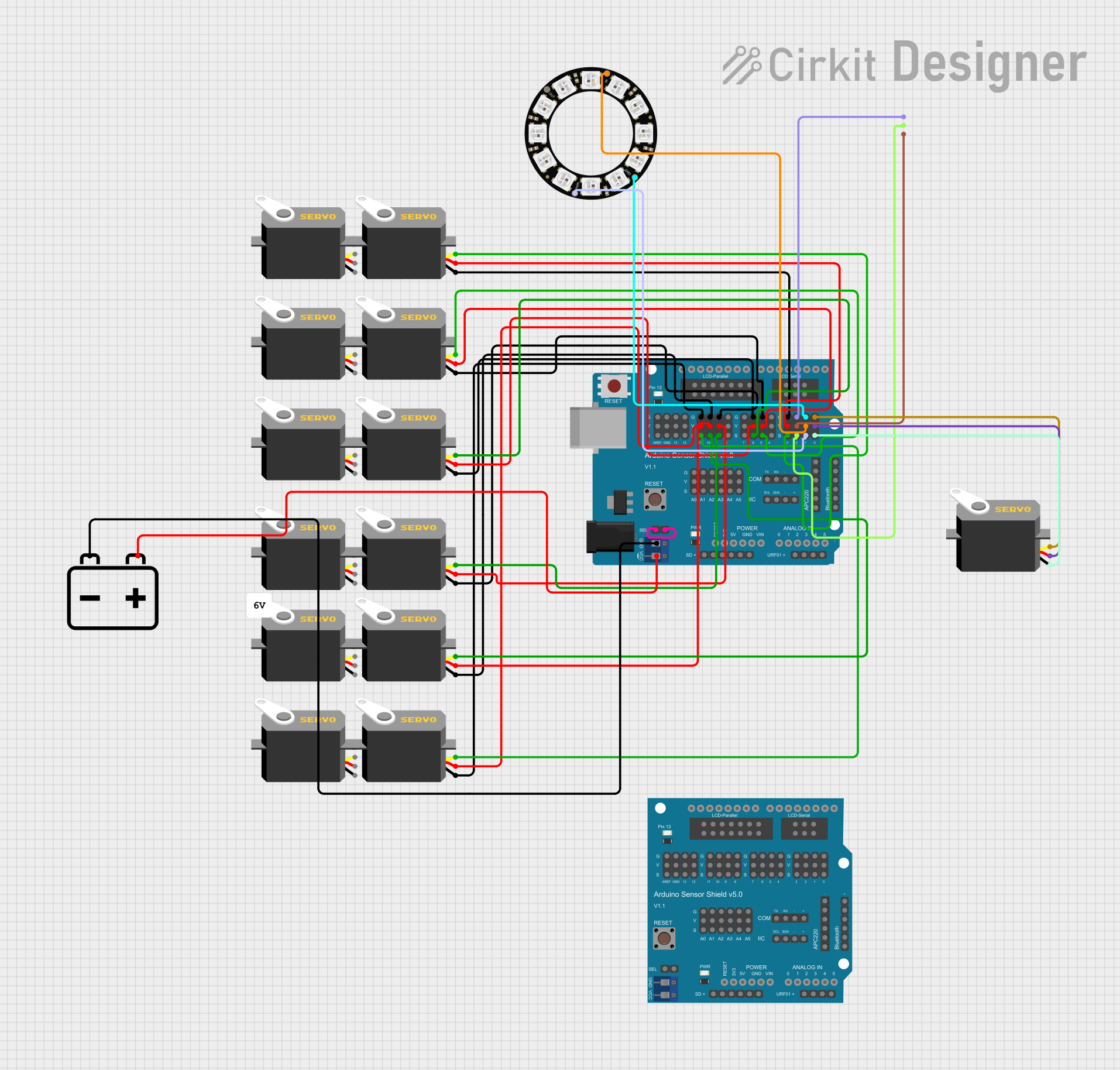 Open Project in Cirkit Designer
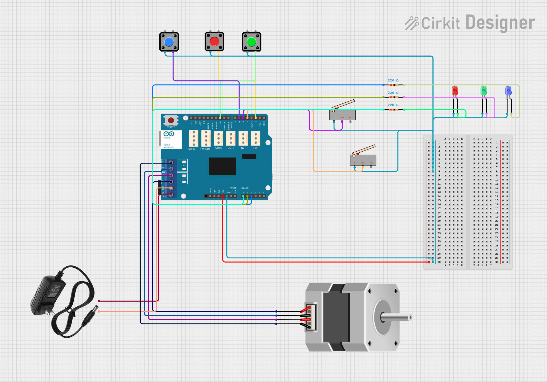 Open Project in Cirkit Designer
Explore Projects Built with SparkFun PWM Shield
Open Project in Cirkit DesignerOpen Project in Cirkit DesignerOpen Project in Cirkit DesignerOpen Project in Cirkit DesignerCommon Applications
- Controlling servo motors in robotics projects
- Driving DC motors with variable speed
- Dimming LEDs for lighting applications
- Generating PWM signals for custom electronics projects
Technical Specifications
The SparkFun PWM Shield is built around the PCA9685 PWM driver IC, which communicates with the Arduino via I2C. Below are the key technical details:
Key Features
- PWM Channels: 16 independent PWM outputs
- PWM Resolution: 12-bit (4096 steps)
- Operating Voltage: 3.3V or 5V (logic level compatible with Arduino)
- Output Voltage: Up to 6V (external power supply required for higher voltage)
- Communication Protocol: I2C (default address: 0x40, configurable)
- Frequency Range: 24 Hz to 1526 Hz
- Current per Channel: Up to 25mA (sink current)
- External Power Input: 5V to 6V (via terminal block for powering servos/motors)
Pin Configuration
The SparkFun PWM Shield connects directly to the Arduino's headers and includes additional pins for external power and I2C communication. Below is the pin configuration:
| Pin Name | Description |
|---|---|
| SDA | I2C Data Line (connects to Arduino SDA pin) |
| SCL | I2C Clock Line (connects to Arduino SCL pin) |
| VCC | Logic voltage input (3.3V or 5V, supplied by Arduino) |
| GND | Ground connection |
| PWM Outputs (0-15) | 16 PWM output channels for controlling servos, motors, or LEDs |
| External Power (+) | Positive terminal for external power supply (5V to 6V for servos/motors) |
| External Power (-) | Ground terminal for external power supply |
Usage Instructions
Connecting the Shield
- Attach the Shield: Plug the SparkFun PWM Shield directly onto the Arduino's headers.
- Power the Shield:
- For low-power applications (e.g., LEDs), the shield can draw power directly from the Arduino.
- For high-power devices (e.g., servos or motors), connect an external 5V-6V power supply to the terminal block.
- Connect Devices: Attach servos, motors, or LEDs to the PWM output pins (0-15).
Programming the Shield
The SparkFun PWM Shield uses the PCA9685 IC, which can be controlled using the Adafruit PCA9685 library. Below is an example Arduino sketch to control a servo motor:
#include <Wire.h>
#include <Adafruit_PWMServoDriver.h>

// Create an instance of the PWM driver
Adafruit_PWMServoDriver pwm = Adafruit_PWMServoDriver();

void setup() {
  pwm.begin(); // Initialize the PWM driver
  pwm.setPWMFreq(50); // Set PWM frequency to 50 Hz (standard for servos)
}

void loop() {
  // Move servo connected to channel 0 to 0 degrees
  pwm.setPWM(0, 0, 150); // Pulse width for 0 degrees
  delay(1000); // Wait 1 second

  // Move servo connected to channel 0 to 90 degrees
  pwm.setPWM(0, 0, 375); // Pulse width for 90 degrees
  delay(1000); // Wait 1 second

  // Move servo connected to channel 0 to 180 degrees
  pwm.setPWM(0, 0, 600); // Pulse width for 180 degrees
  delay(1000); // Wait 1 second
}
Important Considerations
- External Power: Always use an external power supply when driving high-power devices like servos or motors. Ensure the voltage does not exceed 6V.
- I2C Address: The default I2C address is
0x40. If using multiple shields, you can change the address by soldering the address jumpers on the shield. - Frequency Setting: Adjust the PWM frequency based on the application. For servos, use 50 Hz; for LEDs, higher frequencies (e.g., 1 kHz) are recommended to avoid flickering.
Troubleshooting and FAQs
Common Issues
Devices Not Responding
- Cause: Incorrect I2C connection or address conflict.
- Solution: Verify SDA and SCL connections. Check for address conflicts and modify the I2C address if necessary.
Servos/Motors Not Moving
- Cause: Insufficient power supply.
- Solution: Use an external power supply capable of providing sufficient current for all connected devices.
PWM Outputs Not Working
- Cause: Incorrect frequency setting.
- Solution: Ensure the PWM frequency is set appropriately for the connected device (e.g., 50 Hz for servos).
Overheating Components
- Cause: Excessive current draw from connected devices.
- Solution: Ensure each channel does not exceed 25mA sink current. Use external drivers for high-current devices.
FAQs
Q: Can I stack multiple PWM shields?
A: Yes, you can stack multiple shields by configuring unique I2C addresses for each shield using the address jumpers.
Q: What is the maximum number of servos I can control?
A: Each shield can control up to 16 servos. By stacking multiple shields, you can control more servos, limited only by the I2C bus capacity.
Q: Can I use this shield with a 3.3V Arduino (e.g., Arduino Due)?
A: Yes, the shield is compatible with both 3.3V and 5V logic levels.
Q: How do I change the I2C address?
A: Solder the address jumpers on the shield to set a new I2C address. Refer to the PCA9685 datasheet for address configuration details.
This concludes the documentation for the SparkFun PWM Shield. For further assistance, refer to the official SparkFun product page or community forums.