How to Use ESP32: Examples, Pinouts, and Specs
Introduction
The ESP32 is a low-cost, low-power system on a chip (SoC) developed by Espressif Systems. It features integrated Wi-Fi and Bluetooth capabilities, making it an ideal choice for Internet of Things (IoT) applications, smart devices, and embedded systems. The ESP32 is highly versatile, offering dual-core processing, a wide range of GPIO pins, and support for various communication protocols.
Explore Projects Built with ESP32


Explore Projects Built with ESP32
Common Applications and Use Cases
- IoT devices (e.g., smart home systems, environmental monitoring)
- Wireless communication hubs
- Wearable devices
- Robotics and automation
- Data logging and remote sensing
- Prototyping and development of connected systems
Technical Specifications
The ESP32 is packed with features that make it suitable for a wide range of applications. Below are its key technical specifications:
| Feature | Specification |
|---|---|
| Processor | Dual-core Xtensa® 32-bit LX6 microprocessor, up to 240 MHz |
| Wireless Connectivity | Wi-Fi 802.11 b/g/n, Bluetooth v4.2 BR/EDR and BLE |
| Flash Memory | 4 MB (varies by module) |
| SRAM | 520 KB |
| GPIO Pins | Up to 36 GPIO pins (multiplexed with other functions) |
| Operating Voltage | 3.3V |
| Input Voltage Range | 2.2V to 3.6V |
| Power Consumption | Ultra-low power consumption in deep sleep mode (~10 µA) |
| ADC Channels | 18 (12-bit resolution) |
| DAC Channels | 2 |
| Communication Interfaces | UART, SPI, I2C, I2S, CAN, PWM, SDIO |
| Temperature Range | -40°C to 125°C |
| Package | QFN48 (7x7 mm) |
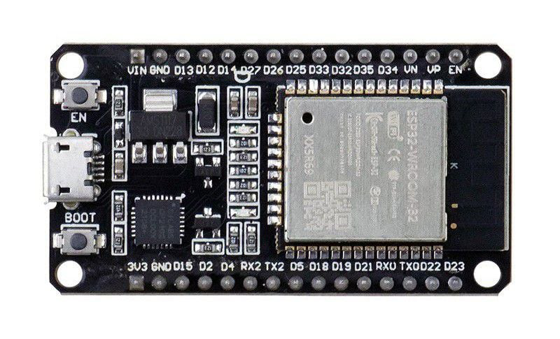
Pin Configuration and Descriptions
The ESP32 has a flexible pinout, with many pins serving multiple functions. Below is a table of commonly used pins and their descriptions:
| Pin | Function | Description |
|---|---|---|
| GPIO0 | Input/Output, Boot Mode Select | Used for boot mode selection during startup. |
| GPIO2 | Input/Output, ADC, PWM | General-purpose pin, supports ADC and PWM. |
| GPIO4 | Input/Output, ADC, PWM | General-purpose pin, supports ADC and PWM. |
| GPIO5 | Input/Output, ADC, PWM | General-purpose pin, supports ADC and PWM. |
| GPIO12 | Input/Output, ADC, Touch Sensor | Can be used as a touch sensor or ADC input. |
| GPIO13 | Input/Output, ADC, Touch Sensor | Can be used as a touch sensor or ADC input. |
| GPIO15 | Input/Output, ADC, PWM | General-purpose pin, supports ADC and PWM. |
| GPIO16 | Input/Output | General-purpose pin. |
| GPIO17 | Input/Output | General-purpose pin. |
| EN | Enable | Active-high enable pin for the ESP32. |
| 3V3 | Power Supply | Provides 3.3V power to the ESP32. |
| GND | Ground | Ground connection. |
Usage Instructions
How to Use the ESP32 in a Circuit
- Powering the ESP32: The ESP32 operates at 3.3V. Ensure your power supply provides a stable 3.3V. If using a development board, you can power it via USB or a 5V input.
- Connecting GPIO Pins: Use the GPIO pins for input/output operations. Be cautious of the voltage levels, as the ESP32 is not 5V-tolerant.
- Programming the ESP32: The ESP32 can be programmed using the Arduino IDE, Espressif's ESP-IDF, or other compatible environments. Install the necessary drivers and libraries for your chosen platform.
- Wi-Fi and Bluetooth Setup: Use the built-in libraries to configure Wi-Fi and Bluetooth for your application. The ESP32 supports both client and access point modes for Wi-Fi.
Important Considerations and Best Practices
- Voltage Levels: Avoid applying voltages higher than 3.3V to the GPIO pins to prevent damage.
- Deep Sleep Mode: Use deep sleep mode to conserve power in battery-powered applications.
- Pull-up/Pull-down Resistors: Some GPIO pins require external pull-up or pull-down resistors for proper operation.
- Boot Mode: Ensure GPIO0 is pulled low during startup to enter programming mode.
Example Code for Arduino IDE
Below is an example of how to connect the ESP32 to a Wi-Fi network and blink an LED:
#include <WiFi.h> // Include the Wi-Fi library

const char* ssid = "Your_SSID";       // Replace with your Wi-Fi SSID
const char* password = "Your_PASSWORD"; // Replace with your Wi-Fi password
const int ledPin = 2;                 // GPIO2 is connected to the onboard LED

void setup() {
  pinMode(ledPin, OUTPUT);            // Set GPIO2 as an output
  Serial.begin(115200);               // Start the serial communication
  Serial.println("Connecting to Wi-Fi...");

  WiFi.begin(ssid, password);         // Connect to the Wi-Fi network
  while (WiFi.status() != WL_CONNECTED) {
    delay(1000);                      // Wait for the connection to establish
    Serial.println("Connecting...");
  }

  Serial.println("Connected to Wi-Fi!");
  Serial.print("IP Address: ");
  Serial.println(WiFi.localIP());     // Print the device's IP address
}

void loop() {
  digitalWrite(ledPin, HIGH);         // Turn the LED on
  delay(1000);                        // Wait for 1 second
  digitalWrite(ledPin, LOW);          // Turn the LED off
  delay(1000);                        // Wait for 1 second
}
Troubleshooting and FAQs
Common Issues and Solutions
ESP32 Not Connecting to Wi-Fi
- Ensure the SSID and password are correct.
- Check if the Wi-Fi network is within range.
- Verify that the router is not blocking the ESP32's MAC address.
GPIO Pins Not Working
- Confirm that the pins are not being used for other functions (e.g., boot mode).
- Check for proper pull-up or pull-down resistors if required.
ESP32 Not Entering Programming Mode
- Ensure GPIO0 is pulled low during startup.
- Verify that the correct COM port and board are selected in the programming environment.
Overheating
- Check for excessive current draw or incorrect power supply voltage.
- Ensure proper ventilation and avoid short circuits.
FAQs
Q: Can the ESP32 operate on 5V?
A: No, the ESP32 operates at 3.3V. However, many development boards include a voltage regulator that allows them to be powered via a 5V input.
Q: How do I reset the ESP32?
A: Press the reset button on the development board or toggle the EN pin.
Q: Can I use the ESP32 with Arduino libraries?
A: Yes, the ESP32 is compatible with many Arduino libraries. Install the ESP32 board package in the Arduino IDE to get started.
Q: What is the maximum range of the ESP32's Wi-Fi?
A: The range depends on environmental factors but typically extends up to 100 meters in open spaces.