
How to Use Arduino Pro Mini (5V): Examples, Pinouts, and Specs
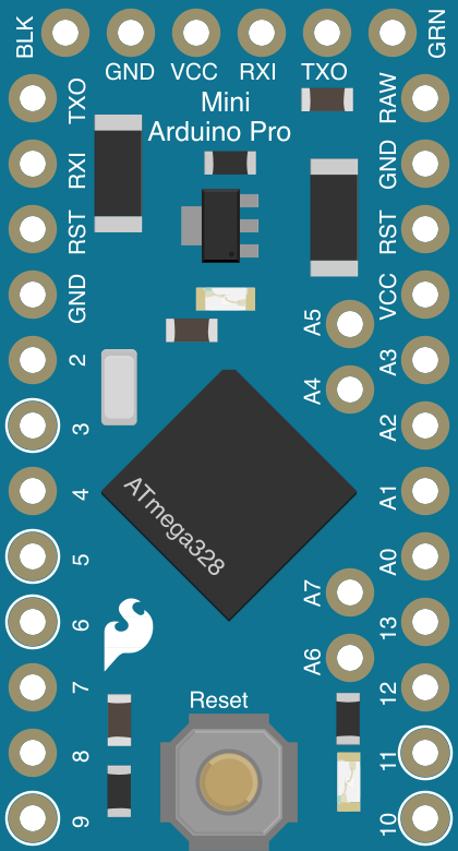
 Design with Arduino Pro Mini (5V) in Cirkit Designer
Introduction
The Arduino Pro Mini (5V), manufactured by SparkFun (Part ID: DEV-11113), is a compact and versatile microcontroller board based on the ATmega328P. Designed for embedded applications, it offers a small form factor while maintaining the core functionality of larger Arduino boards. The Pro Mini is ideal for projects where space is limited, and it is particularly suited for applications requiring low power consumption.
Explore Projects Built with Arduino Pro Mini (5V)
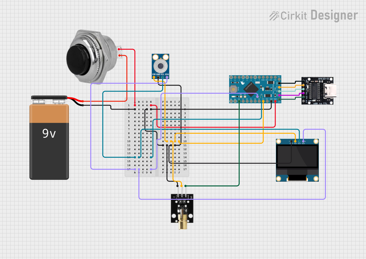 Open Project in Cirkit Designer
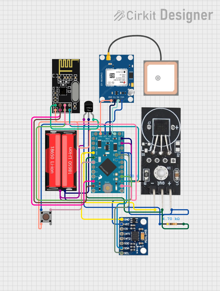 Open Project in Cirkit Designer
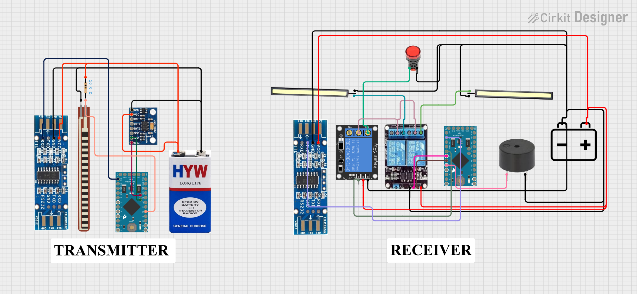 Open Project in Cirkit Designer
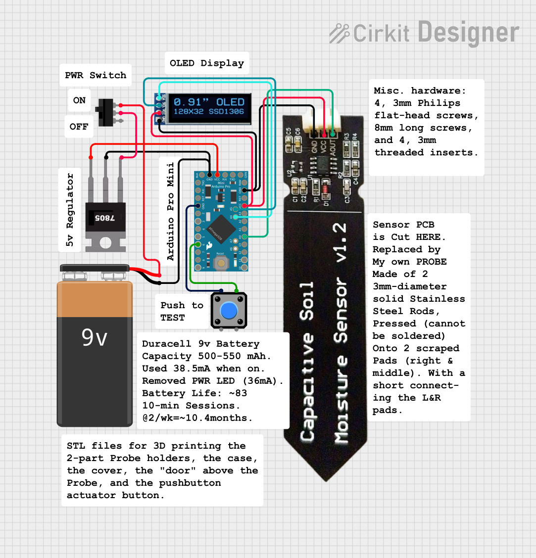 Open Project in Cirkit Designer
Explore Projects Built with Arduino Pro Mini (5V)
Open Project in Cirkit DesignerOpen Project in Cirkit DesignerOpen Project in Cirkit DesignerOpen Project in Cirkit DesignerCommon Applications and Use Cases
- Wearable electronics
- IoT (Internet of Things) devices
- Robotics and automation
- Sensor data acquisition
- Prototyping and small-scale production
Technical Specifications
The Arduino Pro Mini (5V) is designed to operate at 5V logic levels and is powered by the ATmega328P microcontroller. Below are the key technical details:
General Specifications
| Parameter | Value |
|---|---|
| Microcontroller | ATmega328P |
| Operating Voltage | 5V |
| Input Voltage (RAW pin) | 5V to 12V |
| Digital I/O Pins | 14 (6 PWM outputs) |
| Analog Input Pins | 6 |
| Clock Speed | 16 MHz |
| Flash Memory | 32 KB (0.5 KB used by bootloader) |
| SRAM | 2 KB |
| EEPROM | 1 KB |
| Dimensions | 18 mm x 33 mm |
Pin Configuration and Descriptions
The Arduino Pro Mini has a total of 24 pins, including power, analog, and digital I/O pins. Below is the pin configuration:
Power Pins
| Pin Name | Description |
|---|---|
| RAW | Input voltage pin (5V to 12V). Used to power the board via an external source. |
| VCC | Regulated 5V output. Can also be used to power the board directly at 5V. |
| GND | Ground pin. |
| RST | Reset pin. Pulling this pin LOW resets the microcontroller. |
Digital I/O Pins
| Pin Number | Description |
|---|---|
| D0 - D13 | General-purpose digital I/O pins. Pins D3, D5, D6, D9, D10, and D11 support PWM. |
Analog Input Pins
| Pin Number | Description |
|---|---|
| A0 - A5 | Analog input pins. Can also be used as digital I/O pins if needed. |
Communication Pins
| Pin Name | Description |
|---|---|
| TX (D1) | Transmit pin for serial communication. |
| RX (D0) | Receive pin for serial communication. |
Usage Instructions
The Arduino Pro Mini (5V) is designed for advanced users who are comfortable working with external USB-to-serial adapters for programming. Below are the steps to use the board effectively:
Programming the Board
Connect a USB-to-Serial Adapter:
Since the Pro Mini lacks an onboard USB interface, you will need an external USB-to-serial adapter (e.g., FTDI Basic Breakout) to program it. Connect the adapter to the Pro Mini as follows:- Adapter TX → Pro Mini RX
- Adapter RX → Pro Mini TX
- Adapter VCC → Pro Mini VCC
- Adapter GND → Pro Mini GND
- Adapter DTR → Pro Mini GRN (Reset)
Install the Arduino IDE:
Download and install the Arduino IDE from the official Arduino website.Select the Board and Port:
- In the Arduino IDE, go to
Tools > Boardand select Arduino Pro or Pro Mini. - Under
Tools > Processor, select ATmega328P (5V, 16 MHz). - Select the appropriate COM port under
Tools > Port.
- In the Arduino IDE, go to
Upload Code:
Write your code in the Arduino IDE and click the Upload button. The code will be uploaded to the Pro Mini via the USB-to-serial adapter.
Example Code: Blinking an LED
The following example demonstrates how to blink an LED connected to pin D13:
// Blink an LED connected to pin D13
// This example toggles the LED ON and OFF every 1 second.

void setup() {
  pinMode(13, OUTPUT); // Set pin D13 as an output
}

void loop() {
  digitalWrite(13, HIGH); // Turn the LED ON
  delay(1000);            // Wait for 1 second
  digitalWrite(13, LOW);  // Turn the LED OFF
  delay(1000);            // Wait for 1 second
}
Important Considerations and Best Practices
- Power Supply: Ensure the input voltage on the RAW pin does not exceed 12V to avoid damaging the onboard voltage regulator.
- FTDI Adapter Orientation: Double-check the orientation of the FTDI adapter when connecting it to the Pro Mini to prevent incorrect wiring.
- Soldering: The Pro Mini does not come with pre-soldered headers. You will need to solder headers or wires as required for your project.
- Low Power Applications: For battery-powered projects, consider using the sleep modes of the ATmega328P to reduce power consumption.
Troubleshooting and FAQs
Common Issues
The board is not detected by the Arduino IDE:
- Ensure the USB-to-serial adapter drivers are installed correctly.
- Verify that the correct COM port is selected in the Arduino IDE.
Code upload fails with a timeout error:
- Check the connections between the USB-to-serial adapter and the Pro Mini.
- Ensure the correct board and processor are selected in the Arduino IDE.
The board does not power on:
- Verify the input voltage on the RAW or VCC pin.
- Check for loose or incorrect connections.
The LED on pin D13 does not blink:
- Ensure the LED is connected with the correct polarity.
- Verify that the code is uploaded successfully.
FAQs
Q: Can I power the Pro Mini directly with a 5V source?
A: Yes, you can power the board directly via the VCC pin with a regulated 5V source.
Q: Does the Pro Mini support I2C and SPI communication?
A: Yes, the Pro Mini supports both I2C (pins A4 and A5) and SPI (pins D10, D11, D12, and D13) communication protocols.
Q: Can I use the Pro Mini with an external programmer?
A: Yes, you can use an external programmer (e.g., USBasp) to upload code via the ICSP header.
Q: Is the Pro Mini compatible with Arduino shields?
A: No, the Pro Mini does not have the standard Arduino shield form factor. However, you can connect peripherals manually using jumper wires.
By following this documentation, you can effectively integrate the Arduino Pro Mini (5V) into your projects and troubleshoot common issues with ease.