
How to Use DHT11: Examples, Pinouts, and Specs
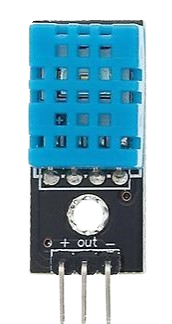
 Design with DHT11 in Cirkit Designer
Introduction
The DHT11 is a digital temperature and humidity sensor that provides accurate readings of temperature in Celsius and humidity in percentage. It is a low-cost, easy-to-use sensor that outputs calibrated digital signals, making it ideal for a wide range of applications. The DHT11 is commonly used in weather stations, HVAC systems, greenhouses, and other projects requiring environmental monitoring.
Explore Projects Built with DHT11
 Open Project in Cirkit Designer
 Open Project in Cirkit Designer
 Open Project in Cirkit Designer
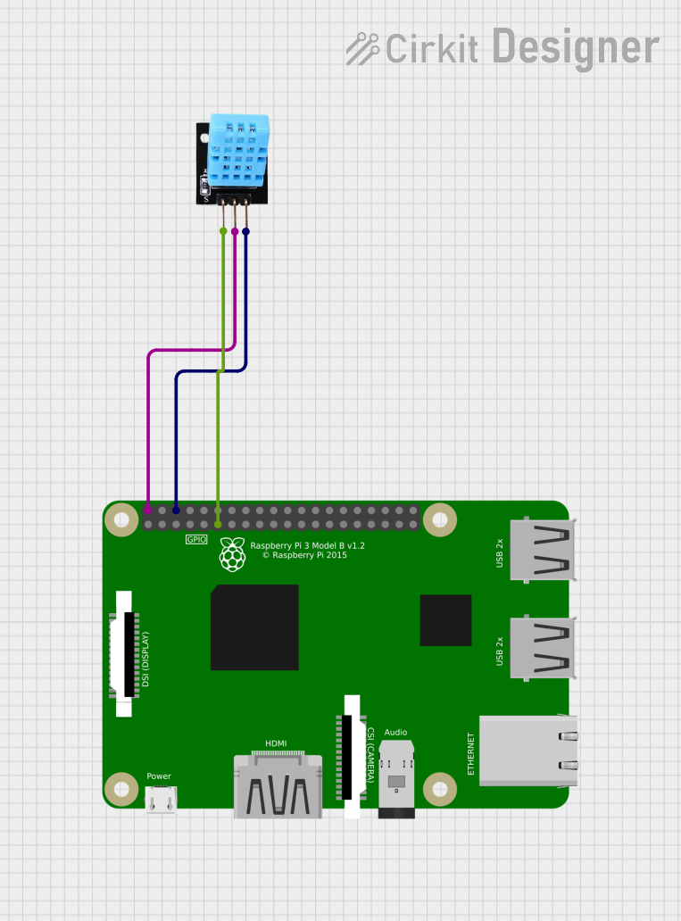 Open Project in Cirkit Designer
Explore Projects Built with DHT11
Open Project in Cirkit DesignerOpen Project in Cirkit DesignerOpen Project in Cirkit DesignerOpen Project in Cirkit DesignerTechnical Specifications
The DHT11 sensor is designed for simplicity and reliability. Below are its key technical specifications:
- Operating Voltage: 3.3V to 5.5V
- Temperature Range: 0°C to 50°C (±2°C accuracy)
- Humidity Range: 20% to 90% RH (±5% accuracy)
- Sampling Rate: 1 Hz (1 reading per second)
- Communication Protocol: Single-wire digital signal
- Dimensions: 15.5mm x 12mm x 5.5mm
Pin Configuration and Descriptions
The DHT11 sensor has four pins, but only three are typically used. Below is the pinout:
| Pin Number | Name | Description |
|---|---|---|
| 1 | VCC | Power supply (3.3V to 5.5V) |
| 2 | DATA | Digital data output (connect to microcontroller) |
| 3 | NC (Not Connected) | No connection (leave unconnected) |
| 4 | GND | Ground |
Usage Instructions
How to Use the DHT11 in a Circuit
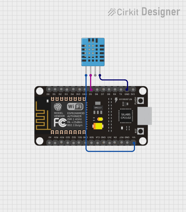
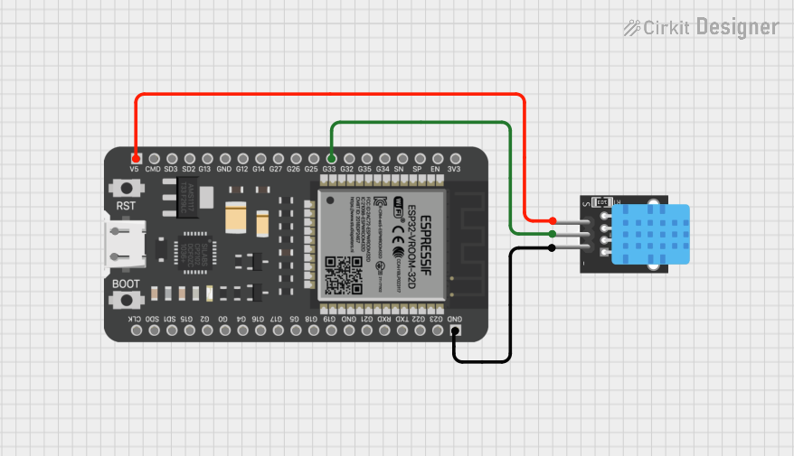
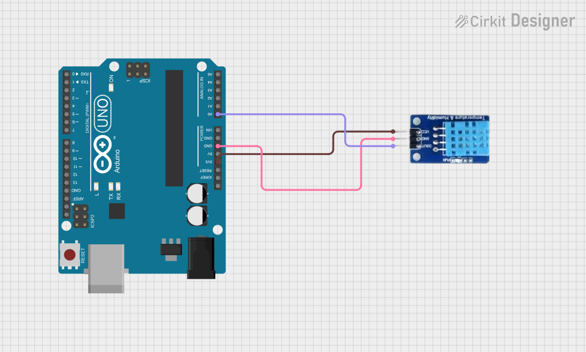
- Power the Sensor: Connect the VCC pin to a 3.3V or 5V power source and the GND pin to ground.
- Connect the Data Pin: Attach the DATA pin to a digital input pin on your microcontroller (e.g., Arduino). Use a 10kΩ pull-up resistor between the DATA pin and VCC to ensure stable communication.
- Read Data: Use a compatible library or write code to read temperature and humidity data from the sensor.
Important Considerations and Best Practices
- Sampling Rate: The DHT11 has a sampling rate of 1 Hz, meaning you should wait at least 1 second between readings.
- Cable Length: Keep the cable length between the sensor and microcontroller as short as possible to avoid signal degradation.
- Environmental Conditions: Avoid exposing the sensor to extreme temperatures or humidity levels beyond its specified range, as this may damage the sensor or reduce accuracy.
- Pull-Up Resistor: Always use a pull-up resistor on the DATA pin to ensure reliable communication.
Example Code for Arduino UNO
Below is an example of how to use the DHT11 sensor with an Arduino UNO. This code uses the popular DHT library.
// Include the DHT library
#include <DHT.h>

// Define the pin where the DHT11 is connected
#define DHTPIN 2  // Connect DATA pin to digital pin 2

// Define the type of DHT sensor
#define DHTTYPE DHT11  // Specify DHT11 sensor

// Initialize the DHT sensor
DHT dht(DHTPIN, DHTTYPE);

void setup() {
  Serial.begin(9600);  // Start serial communication
  Serial.println("DHT11 Sensor Initialization");
  dht.begin();  // Initialize the DHT sensor
}

void loop() {
  // Wait a second between readings
  delay(1000);

  // Read temperature and humidity
  float humidity = dht.readHumidity();
  float temperature = dht.readTemperature();

  // Check if the readings are valid
  if (isnan(humidity) || isnan(temperature)) {
    Serial.println("Failed to read from DHT sensor!");
    return;
  }

  // Print the results to the Serial Monitor
  Serial.print("Humidity: ");
  Serial.print(humidity);
  Serial.print(" %\t");
  Serial.print("Temperature: ");
  Serial.print(temperature);
  Serial.println(" °C");
}
Troubleshooting and FAQs
Common Issues
No Data Output:
- Cause: Incorrect wiring or missing pull-up resistor.
- Solution: Double-check the wiring and ensure a 10kΩ pull-up resistor is connected between the DATA pin and VCC.
Invalid Readings (e.g., NaN):
- Cause: Sensor not initialized properly or communication error.
- Solution: Ensure the sensor is powered correctly and the
dht.begin()function is called in the setup.
Slow Response:
- Cause: Reading data too frequently.
- Solution: Ensure a delay of at least 1 second between readings.
Inaccurate Measurements:
- Cause: Sensor exposed to conditions outside its operating range.
- Solution: Use the sensor within its specified temperature and humidity range.
FAQs
Q: Can I use the DHT11 with a 3.3V microcontroller?
A: Yes, the DHT11 operates within a voltage range of 3.3V to 5.5V, making it compatible with 3.3V microcontrollers.
Q: What is the maximum cable length for the DHT11?
A: The recommended maximum cable length is 20 meters, but shorter lengths are preferred to avoid signal degradation.
Q: How does the DHT11 compare to the DHT22?
A: The DHT22 offers a wider temperature and humidity range with higher accuracy but is more expensive. The DHT11 is sufficient for basic applications.
Q: Can I use multiple DHT11 sensors in one project?
A: Yes, you can use multiple sensors by connecting each DATA pin to a separate digital pin on the microcontroller.