How to Use E220-900T22D LoRa Wireless UART Module RSSI ISM 868MHz 915MHz 22dBm Module LoRa Spread Spectrum UART Interface SMA-K Antenna: Examples, Pinouts, and Specs
Introduction
The E220-900T22D is a high-performance LoRa (Long Range) wireless UART module designed for low-power, long-distance communication. Operating in the ISM frequency bands of 868MHz and 915MHz, this module supports a maximum transmission power of 22dBm and utilizes LoRa spread spectrum technology to achieve robust and reliable communication over extended distances. It features an SMA-K antenna interface for enhanced signal quality and is ideal for applications requiring low power consumption and long-range connectivity.
Explore Projects Built with E220-900T22D LoRa Wireless UART Module RSSI ISM 868MHz 915MHz 22dBm Module LoRa Spread Spectrum UART Interface SMA-K Antenna


Explore Projects Built with E220-900T22D LoRa Wireless UART Module RSSI ISM 868MHz 915MHz 22dBm Module LoRa Spread Spectrum UART Interface SMA-K Antenna
Common Applications
- Internet of Things (IoT) devices
- Smart agriculture and environmental monitoring
- Industrial automation and control systems
- Wireless sensor networks
- Remote data acquisition and telemetry
Technical Specifications
Key Technical Details
| Parameter | Value |
|---|---|
| Frequency Range | 868MHz / 915MHz (ISM Band) |
| Modulation Technique | LoRa Spread Spectrum |
| Transmission Power | Up to 22dBm (160mW) |
| Communication Interface | UART (TTL Level) |
| Operating Voltage | 2.8V to 5.5V |
| Operating Current | 120mA (max) @ 22dBm |
| Sleep Current | < 2µA |
| Sensitivity | -139dBm @ 0.3kbps |
| Data Rate | 0.3kbps to 19.2kbps |
| Antenna Interface | SMA-K Connector |
| Operating Temperature | -40°C to +85°C |
| Dimensions | 24mm x 43mm x 3mm |
Pin Configuration and Descriptions
| Pin Number | Pin Name | Description |
|---|---|---|
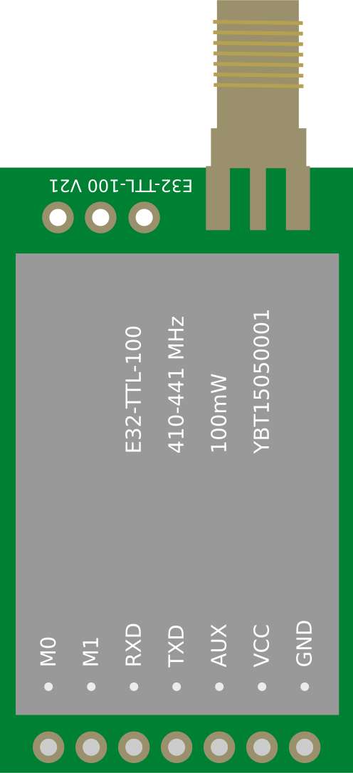
| 1 | M0 | Mode selection pin (used to configure operating modes) |
| 2 | M1 | Mode selection pin (used to configure operating modes) |
| 3 | RXD | UART Receive Data (connect to TXD of the host microcontroller) |
| 4 | TXD | UART Transmit Data (connect to RXD of the host microcontroller) |
| 5 | AUX | Auxiliary pin (indicates module status, e.g., busy or idle) |
| 6 | VCC | Power supply input (2.8V to 5.5V) |
| 7 | GND | Ground |
Usage Instructions
How to Use the E220-900T22D in a Circuit
- Power Supply: Connect the VCC pin to a stable power source (2.8V to 5.5V) and the GND pin to ground.
- UART Connection: Connect the RXD pin of the module to the TXD pin of the host microcontroller and the TXD pin of the module to the RXD pin of the host microcontroller.
- Mode Selection: Use the M0 and M1 pins to configure the module's operating mode:
- Mode 0 (Normal Mode): M0 = 0, M1 = 0
- Mode 1 (Wake-up Mode): M0 = 1, M1 = 0
- Mode 2 (Power-saving Mode): M0 = 0, M1 = 1
- Mode 3 (Configuration Mode): M0 = 1, M1 = 1
- Antenna Connection: Attach an SMA-K antenna to the antenna interface for optimal signal transmission and reception.
- Data Transmission: Send and receive data via the UART interface. Ensure the baud rate and other UART settings match between the module and the host device.
Important Considerations and Best Practices
- Use a high-quality SMA antenna to maximize range and signal quality.
- Avoid placing the module near sources of electromagnetic interference (EMI) to ensure stable communication.
- Configure the module's parameters (e.g., frequency, data rate) using AT commands in Configuration Mode.
- Ensure proper decoupling capacitors are placed near the VCC pin to stabilize the power supply.
Example: Connecting to an Arduino UNO
Below is an example of how to connect and use the E220-900T22D with an Arduino UNO:
Wiring Diagram
| E220-900T22D Pin | Arduino UNO Pin |
|---|---|
| VCC | 5V |
| GND | GND |
| RXD | D3 |
| TXD | D2 |
| M0 | D4 |
| M1 | D5 |
| AUX | Not Connected |
Arduino Code Example
#include <SoftwareSerial.h>

// Define pins for SoftwareSerial
SoftwareSerial LoRaSerial(2, 3); // RX = D2, TX = D3

// Define mode control pins
const int M0 = 4;
const int M1 = 5;

void setup() {
  // Initialize serial communication
  Serial.begin(9600); // For debugging
  LoRaSerial.begin(9600); // For communication with E220-900T22D

  // Set mode control pins as outputs
  pinMode(M0, OUTPUT);
  pinMode(M1, OUTPUT);

  // Set module to Normal Mode (M0 = 0, M1 = 0)
  digitalWrite(M0, LOW);
  digitalWrite(M1, LOW);

  Serial.println("E220-900T22D Initialized in Normal Mode");
}

void loop() {
  // Send data to the module
  LoRaSerial.println("Hello, LoRa!");

  // Check for incoming data from the module
  if (LoRaSerial.available()) {
    String receivedData = LoRaSerial.readString();
    Serial.print("Received: ");
    Serial.println(receivedData);
  }

  delay(1000); // Wait 1 second before sending the next message
}
Troubleshooting and FAQs
Common Issues and Solutions
No Communication Between Devices
- Ensure the RXD and TXD pins are correctly connected to the host microcontroller.
- Verify that the UART baud rate and settings (e.g., parity, stop bits) match between the module and the host.
Short Communication Range
- Check the antenna connection and ensure it is securely attached.
- Avoid obstructions or interference sources in the communication path.
Module Not Responding to AT Commands
- Ensure the module is in Configuration Mode (M0 = 1, M1 = 1).
- Verify the power supply voltage is within the specified range.
High Power Consumption
- Use Power-saving Mode (M0 = 0, M1 = 1) to reduce power consumption during idle periods.
FAQs
Q: Can the module operate at 3.3V?
A: Yes, the module supports a wide operating voltage range of 2.8V to 5.5V.Q: What is the maximum communication distance?
A: The maximum range depends on environmental conditions but can reach up to 5km in open areas with a clear line of sight.Q: How do I reset the module?
A: Toggle the power supply or use the AUX pin to monitor the module's status during reset.
This documentation provides a comprehensive guide to using the E220-900T22D module effectively. For further assistance, refer to the manufacturer's datasheet or support resources.