
How to Use Hirose DF13A 4-Pin Header (Diagram Adapter): Examples, Pinouts, and Specs
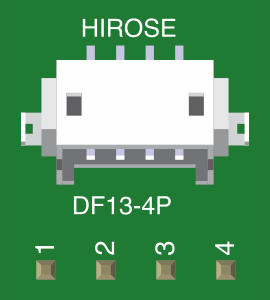
 Design with Hirose DF13A 4-Pin Header (Diagram Adapter) in Cirkit Designer
Introduction
The Hirose DF13A 4-Pin Header, manufactured by Hirose Electric, is a compact and reliable connector designed for securely connecting wires to a circuit board. It features a robust locking mechanism that ensures stable connections, even in environments subject to vibration or movement. Its small form factor makes it ideal for applications where space is limited, while its ease of integration supports a wide range of electronic projects.
Explore Projects Built with Hirose DF13A 4-Pin Header (Diagram Adapter)
 Open Project in Cirkit Designer
 Open Project in Cirkit Designer
 Open Project in Cirkit Designer
 Open Project in Cirkit Designer
Explore Projects Built with Hirose DF13A 4-Pin Header (Diagram Adapter)
Open Project in Cirkit DesignerOpen Project in Cirkit DesignerOpen Project in Cirkit DesignerOpen Project in Cirkit DesignerCommon Applications and Use Cases
- Robotics and automation systems
- Consumer electronics
- Industrial control systems
- Prototyping and development boards
- Connections between sensors, actuators, and microcontrollers
Technical Specifications
Key Technical Details
| Parameter | Value |
|---|---|
| Manufacturer | Hirose Electric |
| Model Number | DF13A |
| Number of Pins | 4 |
| Pitch (Pin Spacing) | 1.25 mm |
| Rated Voltage | 100 V AC/DC |
| Rated Current | 1 A per pin |
| Operating Temperature | -35°C to +85°C |
| Contact Resistance | 30 mΩ max |
| Insulation Resistance | 1000 MΩ min |
| Locking Mechanism | Positive locking system |
| Mounting Style | Through-hole or surface-mount options |
Pin Configuration and Descriptions
The DF13A 4-Pin Header has four pins arranged in a single row with a 1.25 mm pitch. Below is the pin configuration:
| Pin Number | Description | Typical Use Case |
|---|---|---|
| 1 | VCC (Power Supply) | Connect to the positive voltage rail |
| 2 | GND (Ground) | Connect to the ground rail |
| 3 | Signal/Data Line 1 | Transmit or receive data |
| 4 | Signal/Data Line 2 | Transmit or receive data |
Usage Instructions
How to Use the Component in a Circuit
Soldering the Header:
- If using the through-hole version, insert the pins into the PCB holes and solder them securely.
- For the surface-mount version, align the header with the PCB pads and solder carefully to avoid bridging.
Connecting Wires:
- Use a compatible DF13 connector housing with crimped wires to connect to the header.
- Ensure the wires are properly crimped and inserted into the housing to avoid loose connections.
Locking Mechanism:
- When connecting the housing to the header, ensure the locking mechanism clicks into place.
- This prevents accidental disconnection during operation.
Wiring Example:
- Pin 1 (VCC) connects to the power supply.
- Pin 2 (GND) connects to the ground.
- Pins 3 and 4 can be used for data or signal lines, depending on your application.
Important Considerations and Best Practices
- Voltage and Current Ratings: Do not exceed the rated voltage (100 V) or current (1 A per pin) to avoid damage.
- Proper Alignment: Ensure the connector housing is aligned correctly with the header before insertion to prevent pin bending.
- Environmental Conditions: Operate within the specified temperature range (-35°C to +85°C) for optimal performance.
- Crimping Tools: Use the recommended crimping tools for DF13 connectors to ensure reliable wire connections.
Example: Connecting to an Arduino UNO
The DF13A 4-Pin Header can be used to connect sensors or modules to an Arduino UNO. Below is an example of wiring and code for reading data from a sensor connected via the DF13 header.
Wiring Diagram
- Pin 1 (VCC) → Arduino 5V
- Pin 2 (GND) → Arduino GND
- Pin 3 (Signal Line 1) → Arduino Digital Pin 2
- Pin 4 (Signal Line 2) → Arduino Digital Pin 3
Arduino Code Example
// Example code for reading data from a sensor connected via DF13A 4-Pin Header

const int signalPin1 = 2; // Pin 3 of DF13 header connected to Digital Pin 2
const int signalPin2 = 3; // Pin 4 of DF13 header connected to Digital Pin 3

void setup() {
  pinMode(signalPin1, INPUT); // Set signalPin1 as input
  pinMode(signalPin2, INPUT); // Set signalPin2 as input
  Serial.begin(9600); // Initialize serial communication
}

void loop() {
  int data1 = digitalRead(signalPin1); // Read data from signalPin1
  int data2 = digitalRead(signalPin2); // Read data from signalPin2

  // Print the data to the Serial Monitor
  Serial.print("Signal 1: ");
  Serial.println(data1);
  Serial.print("Signal 2: ");
  Serial.println(data2);

  delay(500); // Wait for 500ms before reading again
}
Troubleshooting and FAQs
Common Issues and Solutions
Loose Connections:
- Issue: The connector housing does not stay securely attached to the header.
- Solution: Ensure the locking mechanism clicks into place. Check for damaged or improperly crimped wires.
Bent Pins:
- Issue: Pins are bent during insertion or handling.
- Solution: Carefully straighten the pins using needle-nose pliers. Avoid excessive force during insertion.
Signal Interference:
- Issue: Data signals are noisy or unreliable.
- Solution: Use shielded cables for signal lines and ensure proper grounding.
Overheating:
- Issue: The header becomes hot during operation.
- Solution: Verify that the current does not exceed 1 A per pin. Check for short circuits.
FAQs
Q1: Can I use the DF13A 4-Pin Header for high-frequency signals?
A1: Yes, the DF13A is suitable for high-frequency signals, but ensure proper shielding and grounding to minimize interference.
Q2: What tools are recommended for crimping DF13 connectors?
A2: Use Hirose's recommended crimping tools or equivalent high-quality tools to ensure reliable connections.
Q3: Is the DF13A header compatible with other Hirose DF series connectors?
A3: The DF13A is specifically designed for DF13 series connectors. Compatibility with other DF series connectors may vary.
Q4: Can I use this header in outdoor applications?
A4: The DF13A is not weatherproof. For outdoor use, additional protection such as enclosures or conformal coatings is recommended.