How to Use GNSS GPS L86-M33 Breakout: Examples, Pinouts, and Specs
Introduction
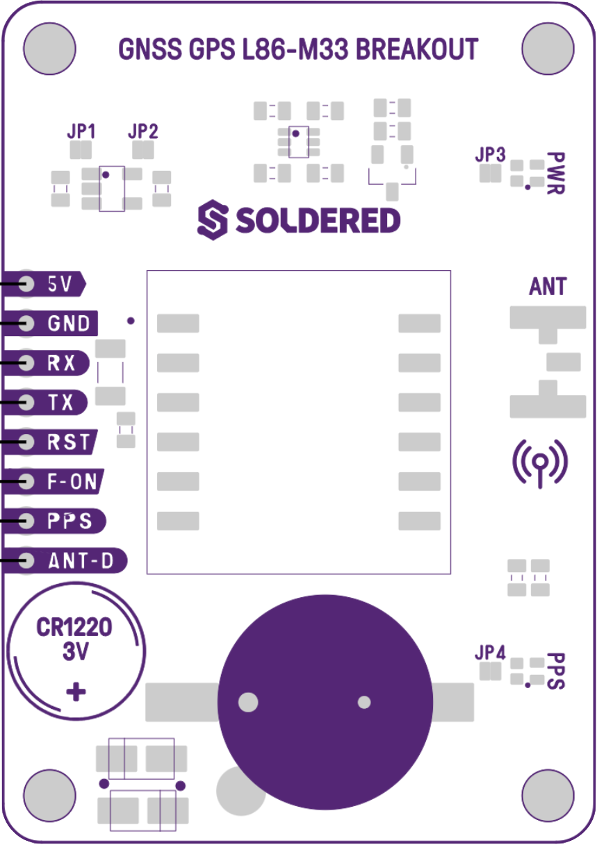
The GNSS GPS L86-M33 Breakout by Soldered (Manufacturer Part ID: GNSS GPS L86-M33 NATIVE) is a compact and highly efficient GPS module designed for accurate positioning and navigation. Utilizing Global Navigation Satellite System (GNSS) technology, this module provides precise location data, making it ideal for a wide range of applications. Its breakout board design ensures easy integration into electronic projects, whether for hobbyists or professional developers.
Explore Projects Built with GNSS GPS L86-M33 Breakout


Explore Projects Built with GNSS GPS L86-M33 Breakout
Common Applications and Use Cases
- Location Tracking: Ideal for vehicle tracking, asset tracking, and personal navigation devices.
- Navigation Systems: Used in drones, robotics, and autonomous vehicles for real-time navigation.
- IoT Projects: Enables geolocation functionality in Internet of Things (IoT) devices.
- Time Synchronization: Provides accurate timing data for systems requiring precise synchronization.
Technical Specifications
Key Technical Details
| Parameter | Value |
|---|---|
| GNSS Technology | GPS, QZSS |
| Frequency Bands | L1 (1575.42 MHz) |
| Positioning Accuracy | < 2.5 meters CEP |
| Cold Start Time | < 35 seconds |
| Hot Start Time | < 1 second |
| Supply Voltage | 3.0V to 4.3V |
| Operating Current | 20 mA (typical) |
| Communication Interface | UART (default baud rate: 9600 bps) |
| Operating Temperature | -40°C to +85°C |
| Dimensions | 16 mm x 16 mm x 6 mm |
Pin Configuration and Descriptions
| Pin Name | Pin Number | Description |
|---|---|---|
| VCC | 1 | Power supply input (3.0V to 4.3V). |
| GND | 2 | Ground connection. |
| TX | 3 | UART Transmit pin (sends data to the host device). |
| RX | 4 | UART Receive pin (receives data from the host). |
| PPS | 5 | Pulse Per Second output for timing synchronization. |
| EN | 6 | Enable pin (active high to power on the module). |
Usage Instructions
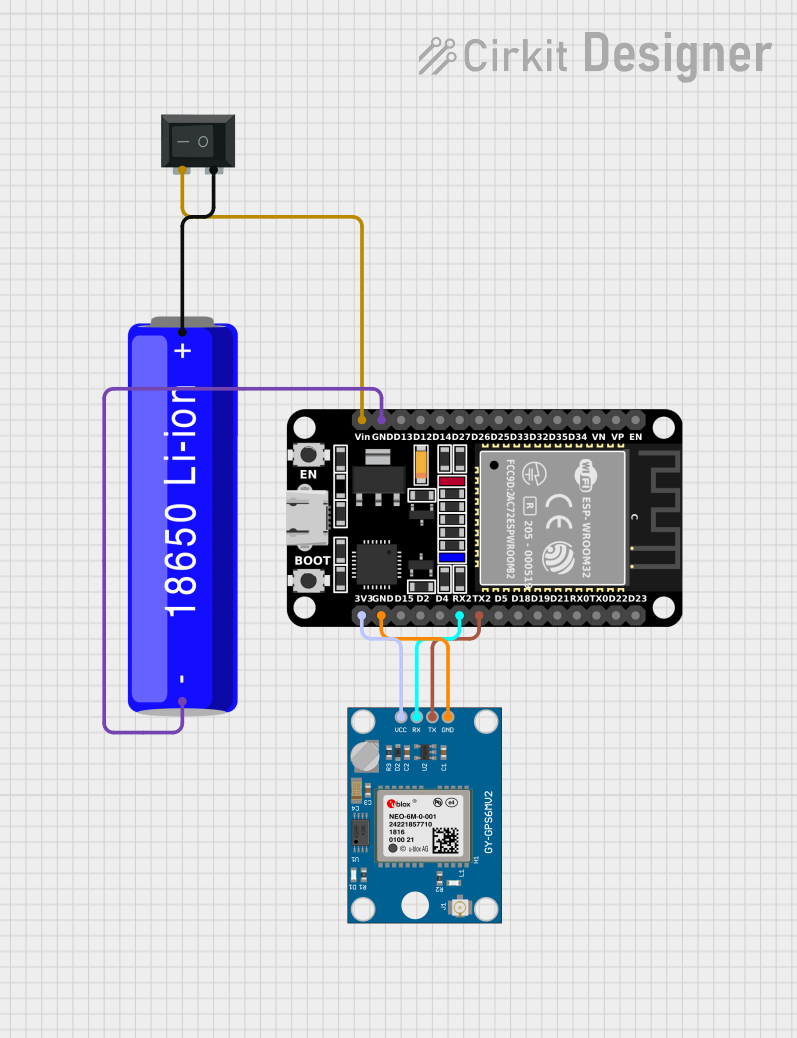
How to Use the GNSS GPS L86-M33 in a Circuit
- Power Supply: Connect the VCC pin to a regulated 3.3V or 4.3V power source and the GND pin to the ground.
- UART Communication: Connect the TX pin of the module to the RX pin of your microcontroller (e.g., Arduino UNO) and the RX pin of the module to the TX pin of the microcontroller.
- Enable the Module: Pull the EN pin high to activate the module.
- Antenna Connection: Ensure the module is connected to an external active antenna for optimal signal reception.
- Data Parsing: Use a microcontroller or computer to read and parse NMEA sentences (standard GPS data format) from the module.
Important Considerations and Best Practices
- Antenna Placement: Place the antenna in an open area with a clear view of the sky for better satellite reception.
- Power Stability: Use a stable power supply to avoid performance issues.
- UART Settings: Ensure the UART baud rate is set to 9600 bps (default) unless reconfigured.
- Environmental Factors: Avoid using the module in areas with heavy RF interference or obstructions.
Example Code for Arduino UNO
Below is an example of how to interface the GNSS GPS L86-M33 with an Arduino UNO to read GPS data:
#include <SoftwareSerial.h>

// Define RX and TX pins for SoftwareSerial
SoftwareSerial gpsSerial(4, 3); // RX = Pin 4, TX = Pin 3

void setup() {
  Serial.begin(9600); // Initialize Serial Monitor at 9600 bps
  gpsSerial.begin(9600); // Initialize GPS module communication at 9600 bps

  Serial.println("GNSS GPS L86-M33 Module Test");
  Serial.println("Waiting for GPS data...");
}

void loop() {
  // Check if data is available from the GPS module
  while (gpsSerial.available()) {
    char gpsData = gpsSerial.read(); // Read one character from GPS module
    Serial.print(gpsData); // Print the character to Serial Monitor

    // Note: GPS data is in NMEA format. Use a GPS library to parse it
    // if you need specific information like latitude, longitude, etc.
  }
}
Troubleshooting and FAQs
Common Issues and Solutions
No GPS Data Received:
- Cause: Poor satellite reception or antenna placement.
- Solution: Ensure the antenna has a clear view of the sky and is properly connected.
Module Not Powering On:
- Cause: Incorrect power supply or EN pin not pulled high.
- Solution: Verify the VCC voltage is within the specified range and ensure the EN pin is high.
Garbage Data on Serial Monitor:
- Cause: Incorrect UART baud rate.
- Solution: Set the baud rate to 9600 bps in both the module and the microcontroller.
Slow GPS Fix:
- Cause: Cold start or poor signal conditions.
- Solution: Allow the module sufficient time to acquire satellite data, especially during the first use.
FAQs
Q: Can the module work indoors?
- A: The module may work indoors near windows, but performance will be significantly reduced compared to outdoor use.
Q: How do I parse NMEA sentences?
- A: Use a GPS library like TinyGPS++ to extract specific data such as latitude, longitude, and time from NMEA sentences.
Q: Can I change the default baud rate?
- A: Yes, the baud rate can be reconfigured using specific commands sent to the module.
Q: What is the PPS pin used for?
- A: The PPS pin outputs a precise pulse every second, which can be used for time synchronization in applications requiring high accuracy.
This concludes the documentation for the GNSS GPS L86-M33 Breakout. For further assistance, refer to the manufacturer's datasheet or contact Soldered support.