Cirkit Designer Logo
Cirkit Designer
Your all-in-one circuit design IDE
Home / 
Component Documentation

How to Use MCP73871: Examples, Pinouts, and Specs

Image of MCP73871
Cirkit Designer LogoDesign with MCP73871 in Cirkit Designer

Introduction

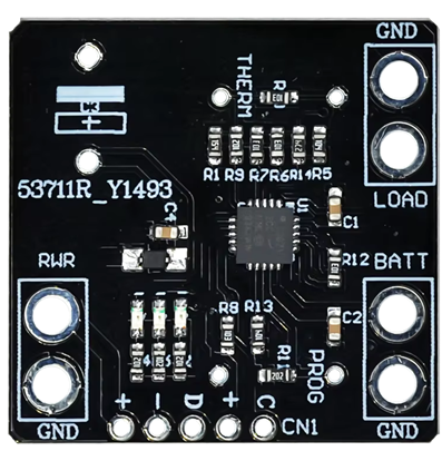
The MCP73871 is a highly integrated Li-Ion/Li-Polymer battery charge management controller with an integrated power path selector. It is designed for space-limited and cost-sensitive applications. This component is ideal for managing the charging process of single-cell Li-Ion or Li-Polymer batteries, ensuring safe and efficient charging while providing power to the system.

Explore Projects Built with MCP73871

Use Cirkit Designer to design, explore, and prototype these projects online. Some projects support real-time simulation. Click "Open Project" to start designing instantly!
ESP32-Based Vibration Motor Controller with I2C IO Expansion
Image of VIBRATYION: A project utilizing MCP73871 in a practical application
This circuit features an ESP32 Wroom Dev Kit microcontroller interfaced with an MCP23017 I/O expansion board via I2C communication, utilizing GPIO 21 and GPIO 22 for SDA and SCL lines, respectively. A vibration motor is controlled by an NPN transistor acting as a switch, with a diode for back EMF protection and a resistor to limit base current. The ESP32 can control the motor by sending signals to the MCP23017, which then interfaces with the transistor to turn the motor on or off.
Cirkit Designer LogoOpen Project in Cirkit Designer
Battery-Powered Raspberry Pi Pico GPS Tracker with Sensor Integration
Image of Copy of CanSet v1: A project utilizing MCP73871 in a practical application
This circuit is a data acquisition and communication system powered by a LiPoly battery and managed by a Raspberry Pi Pico. It includes sensors (BMP280, MPU9250) for environmental data, a GPS module for location tracking, an SD card for data storage, and a WLR089-CanSAT for wireless communication. The TP4056 module handles battery charging, and a toggle switch controls power distribution.
Cirkit Designer LogoOpen Project in Cirkit Designer
Wi-Fi Controlled Relay Module with ESP8266 and MCP23017
Image of smart home: A project utilizing MCP73871 in a practical application
This circuit is a WiFi-enabled relay control system using an ESP8266-01 module and an MCP23017 I/O expander. The ESP8266 communicates with the MCP23017 via I2C to control an 8-channel relay module based on the state of 8 rocker switches, allowing for remote and manual control of connected devices.
Cirkit Designer LogoOpen Project in Cirkit Designer
I2C-Controlled Relay Switching with ESP32 and MCP23017 for Home Automation
Image of Vloerverwarming: A project utilizing MCP73871 in a practical application
This circuit appears to be a control system utilizing two MCP23017 I/O expanders interfaced with an Olimex ESP32-EVB microcontroller via I2C communication, as indicated by the SDA and SCL connections with pull-up resistors. The MCP23017 expanders control an 8-channel relay module, allowing the microcontroller to switch various loads, potentially for home automation or industrial control. Additionally, there is an Adafruit ADS1115 16-bit ADC for analog signal measurement, and several heating actuators and a thermostat are connected, suggesting temperature control functionality.
Cirkit Designer LogoOpen Project in Cirkit Designer

Explore Projects Built with MCP73871

Use Cirkit Designer to design, explore, and prototype these projects online. Some projects support real-time simulation. Click "Open Project" to start designing instantly!
Image of VIBRATYION: A project utilizing MCP73871 in a practical application
ESP32-Based Vibration Motor Controller with I2C IO Expansion
This circuit features an ESP32 Wroom Dev Kit microcontroller interfaced with an MCP23017 I/O expansion board via I2C communication, utilizing GPIO 21 and GPIO 22 for SDA and SCL lines, respectively. A vibration motor is controlled by an NPN transistor acting as a switch, with a diode for back EMF protection and a resistor to limit base current. The ESP32 can control the motor by sending signals to the MCP23017, which then interfaces with the transistor to turn the motor on or off.
Cirkit Designer LogoOpen Project in Cirkit Designer
Image of Copy of CanSet v1: A project utilizing MCP73871 in a practical application
Battery-Powered Raspberry Pi Pico GPS Tracker with Sensor Integration
This circuit is a data acquisition and communication system powered by a LiPoly battery and managed by a Raspberry Pi Pico. It includes sensors (BMP280, MPU9250) for environmental data, a GPS module for location tracking, an SD card for data storage, and a WLR089-CanSAT for wireless communication. The TP4056 module handles battery charging, and a toggle switch controls power distribution.
Cirkit Designer LogoOpen Project in Cirkit Designer
Image of smart home: A project utilizing MCP73871 in a practical application
Wi-Fi Controlled Relay Module with ESP8266 and MCP23017
This circuit is a WiFi-enabled relay control system using an ESP8266-01 module and an MCP23017 I/O expander. The ESP8266 communicates with the MCP23017 via I2C to control an 8-channel relay module based on the state of 8 rocker switches, allowing for remote and manual control of connected devices.
Cirkit Designer LogoOpen Project in Cirkit Designer
Image of Vloerverwarming: A project utilizing MCP73871 in a practical application
I2C-Controlled Relay Switching with ESP32 and MCP23017 for Home Automation
This circuit appears to be a control system utilizing two MCP23017 I/O expanders interfaced with an Olimex ESP32-EVB microcontroller via I2C communication, as indicated by the SDA and SCL connections with pull-up resistors. The MCP23017 expanders control an 8-channel relay module, allowing the microcontroller to switch various loads, potentially for home automation or industrial control. Additionally, there is an Adafruit ADS1115 16-bit ADC for analog signal measurement, and several heating actuators and a thermostat are connected, suggesting temperature control functionality.
Cirkit Designer LogoOpen Project in Cirkit Designer

Common Applications and Use Cases

  • Portable electronic devices
  • Wearable technology
  • Handheld instruments
  • Backup battery systems
  • USB-powered devices

Technical Specifications

Key Technical Details

Parameter Value
Input Voltage Range 3.75V to 6V
Battery Charge Voltage 4.2V (typical)
Charge Current Programmable up to 1.8A
Power Path Selector Integrated
Operating Temperature -40°C to +85°C
Package 20-Lead QFN (4x4 mm)

Pin Configuration and Descriptions

Pin Number Pin Name Description
1 VDD Input supply voltage
2 VBAT Battery connection
3 VSS Ground
4 PROG Charge current programming
5 STAT1 Charge status indicator 1
6 STAT2 Charge status indicator 2
7 CE Charge enable
8 TE Termination enable
9 PG Power good indicator
10 THERM Thermistor input for battery temperature sensing
11 VUSB USB input voltage
12 VBUS Bus voltage input
13 VOUT Output voltage
14 ISET Charge current set
15 EN Enable
16 PSEL Power source selection
17 D+ USB D+ line
18 D- USB D- line
19 NC No connection
20 NC No connection

Usage Instructions

How to Use the MCP73871 in a Circuit

  1. Power Supply Connection: Connect the input supply voltage (3.75V to 6V) to the VDD pin.
  2. Battery Connection: Connect the battery to the VBAT pin.
  3. Ground Connection: Connect the VSS pin to the ground of the circuit.
  4. Programming Charge Current: Use a resistor between the PROG pin and ground to set the desired charge current.
  5. Status Indicators: Connect LEDs to STAT1 and STAT2 pins to monitor the charging status.
  6. Enable Charging: Use the CE pin to enable or disable charging.
  7. Thermistor Connection: Connect a thermistor to the THERM pin for battery temperature monitoring.
  8. USB and Bus Voltage: Connect the USB input voltage to the VUSB pin and the bus voltage to the VBUS pin.
  9. Output Voltage: The VOUT pin provides the regulated output voltage.

Important Considerations and Best Practices

  • Ensure proper heat dissipation by using a suitable PCB layout with thermal vias.
  • Use appropriate decoupling capacitors on the VDD and VBAT pins to filter out noise.
  • Monitor the battery temperature using a thermistor to prevent overheating.
  • Follow the recommended resistor values for programming the charge current to avoid overcharging the battery.

Troubleshooting and FAQs

Common Issues and Solutions

  1. Issue: The battery is not charging.

    • Solution: Check the input voltage at the VDD pin. Ensure it is within the specified range (3.75V to 6V). Verify the connections to the battery and the ground.
  2. Issue: The charge current is too low.

    • Solution: Verify the resistor value connected to the PROG pin. Ensure it is correctly set to achieve the desired charge current.
  3. Issue: The charge status indicators (STAT1 and STAT2) are not working.

    • Solution: Check the connections to the LEDs. Ensure they are connected correctly and not damaged.
  4. Issue: The device is overheating.

    • Solution: Ensure proper heat dissipation by using a suitable PCB layout with thermal vias. Monitor the battery temperature using a thermistor.

FAQs

  1. Can the MCP73871 be used with a 2-cell battery?

    • No, the MCP73871 is designed for single-cell Li-Ion or Li-Polymer batteries only.
  2. What is the maximum charge current supported by the MCP73871?

    • The MCP73871 supports a programmable charge current up to 1.8A.
  3. How do I select the power source (USB or bus voltage)?

    • Use the PSEL pin to select the power source. Refer to the datasheet for detailed instructions on configuring the PSEL pin.

Example Code for Arduino UNO

Here is an example code to monitor the charging status using an Arduino UNO:

// Define pin connections
const int stat1Pin = 2; // STAT1 connected to digital pin 2
const int stat2Pin = 3; // STAT2 connected to digital pin 3

void setup() {
  // Initialize serial communication
  Serial.begin(9600);
  
  // Set pin modes
  pinMode(stat1Pin, INPUT);
  pinMode(stat2Pin, INPUT);
}

void loop() {
  // Read the status pins
  int stat1 = digitalRead(stat1Pin);
  int stat2 = digitalRead(stat2Pin);
  
  // Print the charging status
  if (stat1 == LOW && stat2 == HIGH) {
    Serial.println("Charging in progress");
  } else if (stat1 == HIGH && stat2 == LOW) {
    Serial.println("Charge complete");
  } else {
    Serial.println("No battery or fault");
  }
  
  // Wait for a second before the next reading
  delay(1000);
}

This code reads the status pins (STAT1 and STAT2) and prints the charging status to the serial monitor. Connect the STAT1 and STAT2 pins of the MCP73871 to the digital pins 2 and 3 of the Arduino UNO, respectively.

By following this documentation, users can effectively integrate the MCP73871 into their projects, ensuring safe and efficient battery charging management.