Cirkit Designer Logo
Cirkit Designer
Your all-in-one circuit design IDE
Home / 
Component Documentation

How to Use Here4 Blue Multiband RTK GNSS: Examples, Pinouts, and Specs


Image of Here4 Blue Multiband RTK GNSS
Cirkit Designer LogoDesign with Here4 Blue Multiband RTK GNSS in Cirkit Designer

Introduction

The Here4 Blue Multiband RTK GNSS (Manufacturer Part ID: CP-06279) is a high-precision Global Navigation Satellite System (GNSS) receiver developed by CubePilot. It supports multiple frequency bands and Real-Time Kinematic (RTK) technology, enabling centimeter-level positioning accuracy. This component is ideal for applications requiring precise navigation and positioning, such as surveying, mapping, autonomous vehicles, and robotics.

Explore Projects Built with Here4 Blue Multiband RTK GNSS
Use Cirkit Designer to design, explore, and prototype these projects online. Some projects support real-time simulation. Click "Open Project" to start designing instantly!
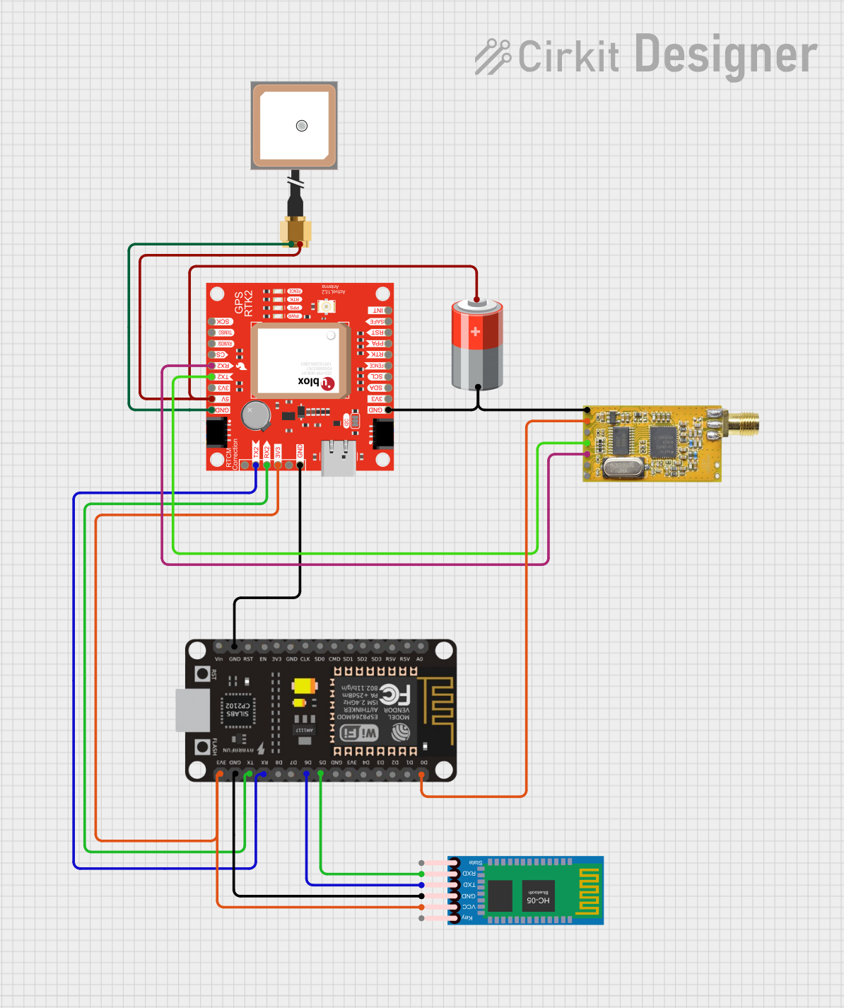
ESP8266 and GPS-RTK2 Based Real-Time GPS Tracker with Bluetooth and APC220 Communication
Image of PANDURTKU0001_1: A project utilizing Here4 Blue Multiband RTK GNSS in a practical application
This circuit integrates a GPS module, an ESP8266 microcontroller, a Bluetooth module, and an APC220 RF module to collect and transmit GPS data. The ESP8266 reads GPS data from the SparkFun Qwiic GPS-RTK2 module and can communicate this data via Bluetooth and RF transmission. The system is powered by a 5V battery and includes an embedded GPS antenna for signal reception.
Cirkit Designer LogoOpen Project in Cirkit Designer
Satellite-Based Timing and Navigation System with SDR and Atomic Clock Synchronization
Image of GPS 시스템 측정 구성도_Confirm: A project utilizing Here4 Blue Multiband RTK GNSS in a practical application
This circuit appears to be a complex system involving power supply management, GPS and timing synchronization, and data communication. It includes a SI-TEX G1 Satellite Compass for GPS data, an XHTF1021 Atomic Rubidium Clock for precise timing, and Ettus USRP B200 units for software-defined radio communication. Power is supplied through various SMPS units and distributed via terminal blocks and DC jacks. Data communication is facilitated by Beelink MINI S12 N95 computers, RS232 splitters, and a 1000BASE-T Media Converter for network connectivity. RF Directional Couplers are used to interface antennas with the USRP units, and the entire system is likely contained within cases for protection and organization.
Cirkit Designer LogoOpen Project in Cirkit Designer
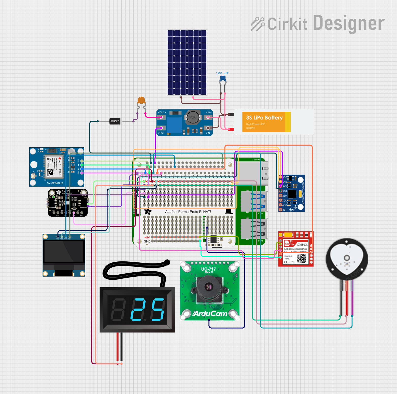
Raspberry Pi 4B-Based Smart Health Monitoring System with GPS and GSM
Image of Accident Detection and Health Monitoring System: A project utilizing Here4 Blue Multiband RTK GNSS in a practical application
This circuit integrates a Raspberry Pi 4B with various sensors and modules, including a GPS module, a GSM module, a heart pulse sensor, an accelerometer, a barometric pressure sensor, and an OLED display. The system captures environmental data, monitors heart pulse, and can send emergency SMS alerts based on sensor readings, with power supplied by a LiPo battery and a solar panel.
Cirkit Designer LogoOpen Project in Cirkit Designer
Satellite Compass and Network-Integrated GPS Data Processing System
Image of GPS 시스템 측정 구성도_241016: A project utilizing Here4 Blue Multiband RTK GNSS in a practical application
This circuit comprises a satellite compass, a mini PC, two GPS antennas, power supplies, a network switch, media converters, and an atomic rubidium clock. The satellite compass is powered by a triple output DC power supply and interfaces with an RS232 splitter for 1PPS signals. The mini PCs are connected to the USRP B200 devices via USB for data and power, and to media converters via Ethernet, which in turn connect to a network switch using fiber optic links. The antennas are connected to the USRP B200s through RF directional couplers, and the atomic clock provides a 1PPS input to the RS232 splitter.
Cirkit Designer LogoOpen Project in Cirkit Designer

Explore Projects Built with Here4 Blue Multiband RTK GNSS

Use Cirkit Designer to design, explore, and prototype these projects online. Some projects support real-time simulation. Click "Open Project" to start designing instantly!
Image of PANDURTKU0001_1: A project utilizing Here4 Blue Multiband RTK GNSS in a practical application
ESP8266 and GPS-RTK2 Based Real-Time GPS Tracker with Bluetooth and APC220 Communication
This circuit integrates a GPS module, an ESP8266 microcontroller, a Bluetooth module, and an APC220 RF module to collect and transmit GPS data. The ESP8266 reads GPS data from the SparkFun Qwiic GPS-RTK2 module and can communicate this data via Bluetooth and RF transmission. The system is powered by a 5V battery and includes an embedded GPS antenna for signal reception.
Cirkit Designer LogoOpen Project in Cirkit Designer
Image of GPS 시스템 측정 구성도_Confirm: A project utilizing Here4 Blue Multiband RTK GNSS in a practical application
Satellite-Based Timing and Navigation System with SDR and Atomic Clock Synchronization
This circuit appears to be a complex system involving power supply management, GPS and timing synchronization, and data communication. It includes a SI-TEX G1 Satellite Compass for GPS data, an XHTF1021 Atomic Rubidium Clock for precise timing, and Ettus USRP B200 units for software-defined radio communication. Power is supplied through various SMPS units and distributed via terminal blocks and DC jacks. Data communication is facilitated by Beelink MINI S12 N95 computers, RS232 splitters, and a 1000BASE-T Media Converter for network connectivity. RF Directional Couplers are used to interface antennas with the USRP units, and the entire system is likely contained within cases for protection and organization.
Cirkit Designer LogoOpen Project in Cirkit Designer
Image of Accident Detection and Health Monitoring System: A project utilizing Here4 Blue Multiband RTK GNSS in a practical application
Raspberry Pi 4B-Based Smart Health Monitoring System with GPS and GSM
This circuit integrates a Raspberry Pi 4B with various sensors and modules, including a GPS module, a GSM module, a heart pulse sensor, an accelerometer, a barometric pressure sensor, and an OLED display. The system captures environmental data, monitors heart pulse, and can send emergency SMS alerts based on sensor readings, with power supplied by a LiPo battery and a solar panel.
Cirkit Designer LogoOpen Project in Cirkit Designer
Image of GPS 시스템 측정 구성도_241016: A project utilizing Here4 Blue Multiband RTK GNSS in a practical application
Satellite Compass and Network-Integrated GPS Data Processing System
This circuit comprises a satellite compass, a mini PC, two GPS antennas, power supplies, a network switch, media converters, and an atomic rubidium clock. The satellite compass is powered by a triple output DC power supply and interfaces with an RS232 splitter for 1PPS signals. The mini PCs are connected to the USRP B200 devices via USB for data and power, and to media converters via Ethernet, which in turn connect to a network switch using fiber optic links. The antennas are connected to the USRP B200s through RF directional couplers, and the atomic clock provides a 1PPS input to the RS232 splitter.
Cirkit Designer LogoOpen Project in Cirkit Designer

Common Applications

  • Surveying and geospatial mapping
  • Autonomous vehicle navigation
  • Precision agriculture
  • Drone flight control systems
  • Robotics requiring high-accuracy localization

Technical Specifications

Key Technical Details

Parameter Specification
Manufacturer CubePilot
Part ID CP-06279
GNSS Support GPS, GLONASS, Galileo, BeiDou, QZSS
Frequency Bands L1, L2, L5
Positioning Accuracy Centimeter-level (with RTK)
Update Rate Up to 10 Hz
Communication Interfaces UART, I2C, CAN
Input Voltage 5V DC
Power Consumption < 1W
Operating Temperature -40°C to 85°C
Dimensions 50mm x 50mm x 15mm
Weight 35g

Pin Configuration and Descriptions

The Here4 Blue Multiband RTK GNSS features a standard connector with the following pinout:

Pin Number Pin Name Description
1 VCC Power input (5V DC)
2 GND Ground
3 TX UART Transmit (data output)
4 RX UART Receive (data input)
5 CAN_H CAN bus high signal
6 CAN_L CAN bus low signal
7 I2C_SCL I2C clock line
8 I2C_SDA I2C data line

Usage Instructions

How to Use the Component in a Circuit

  1. Power Supply: Connect the VCC pin to a stable 5V DC power source and the GND pin to ground.
  2. Communication Interface: Choose one of the supported communication interfaces (UART, I2C, or CAN):
    • For UART, connect the TX and RX pins to the corresponding UART pins on your microcontroller.
    • For I2C, connect the I2C_SCL and I2C_SDA pins to the I2C bus of your microcontroller.
    • For CAN, connect the CAN_H and CAN_L pins to the CAN bus.
  3. Antenna Connection: Attach a compatible GNSS antenna to the SMA connector for optimal signal reception.
  4. RTK Setup: If using RTK, configure the base station and rover settings as per your application requirements.

Important Considerations and Best Practices

  • Antenna Placement: Ensure the GNSS antenna is placed in an open area with a clear view of the sky for optimal satellite reception.
  • Power Supply: Use a stable and noise-free 5V power source to avoid interference with GNSS signals.
  • RTK Configuration: For RTK functionality, ensure the base station and rover are properly synchronized and within communication range.
  • Firmware Updates: Regularly check for firmware updates from CubePilot to ensure compatibility and performance improvements.

Example: Connecting to an Arduino UNO

Below is an example of how to interface the Here4 Blue Multiband RTK GNSS with an Arduino UNO using UART:

#include <SoftwareSerial.h>

// Define RX and TX pins for SoftwareSerial
SoftwareSerial GNSSSerial(10, 11); // RX = pin 10, TX = pin 11

void setup() {
  // Initialize serial communication with GNSS module
  GNSSSerial.begin(9600); // Set baud rate to 9600 (adjust if needed)
  
  // Initialize serial communication with PC for debugging
  Serial.begin(9600);
  Serial.println("Here4 Blue Multiband RTK GNSS Test");
}

void loop() {
  // Check if data is available from the GNSS module
  if (GNSSSerial.available()) {
    // Read data from GNSS module
    String gnssData = GNSSSerial.readString();
    
    // Print GNSS data to the Serial Monitor
    Serial.println(gnssData);
  }
}

Note: Adjust the baud rate in the code to match the default baud rate of the GNSS module.

Troubleshooting and FAQs

Common Issues and Solutions

  1. No GNSS Signal Detected:

    • Ensure the antenna is properly connected and placed in an open area with a clear view of the sky.
    • Verify that the power supply is stable and noise-free.
  2. RTK Not Working:

    • Check the base station configuration and ensure it is transmitting correction data.
    • Verify that the rover is within the communication range of the base station.
  3. No Data Output:

    • Confirm that the communication interface (UART, I2C, or CAN) is correctly configured.
    • Check the wiring and ensure the correct pins are connected.
  4. Intermittent Signal Loss:

    • Avoid placing the GNSS module near sources of electromagnetic interference (e.g., motors, power lines).
    • Use a high-quality GNSS antenna and cables.

FAQs

Q: Can the Here4 Blue Multiband RTK GNSS be used indoors?
A: GNSS signals are weak indoors, so the module is best used outdoors. For indoor applications, consider using a GNSS repeater or alternative positioning systems.

Q: What is the maximum range for RTK communication?
A: The range depends on the communication method used (e.g., radio, Wi-Fi). Typically, RTK communication works within a few kilometers when using a radio link.

Q: How do I update the firmware?
A: Firmware updates can be downloaded from CubePilot's official website. Follow the provided instructions to update the module via the appropriate interface.

Q: Is the module compatible with Pixhawk flight controllers?
A: Yes, the Here4 Blue Multiband RTK GNSS is fully compatible with Pixhawk and other CubePilot flight controllers.