How to Use SparkCore: Examples, Pinouts, and Specs
Introduction
The SparkCore is a microcontroller platform developed by Particle (Manufacturer Part ID: 1.0) specifically designed for Internet of Things (IoT) applications. It features built-in Wi-Fi connectivity and a cloud-based development environment, making it an ideal choice for creating connected devices with ease. The SparkCore simplifies the process of integrating hardware with the internet, enabling rapid prototyping and deployment of IoT solutions.
Explore Projects Built with SparkCore

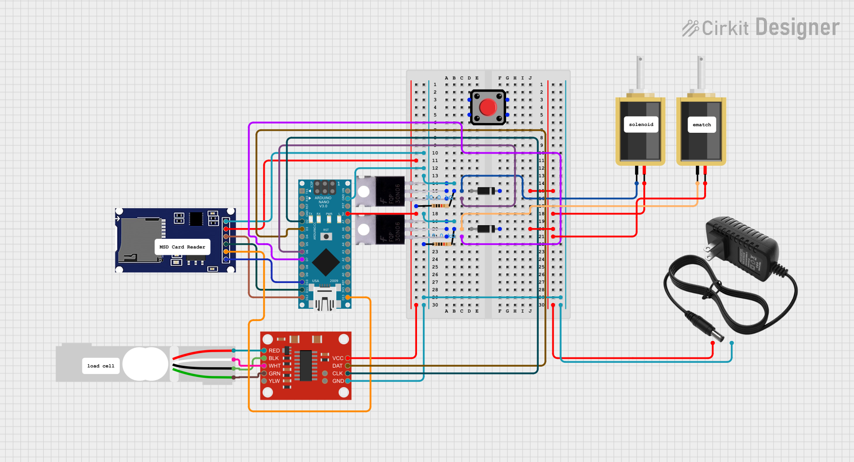

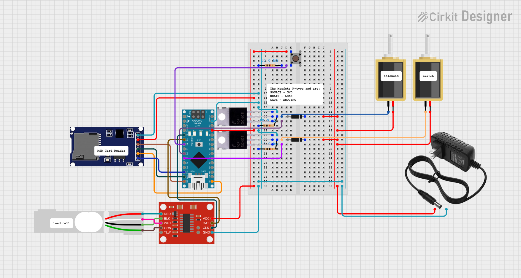
Explore Projects Built with SparkCore
Common Applications and Use Cases
- Smart home automation (e.g., connected lighting, thermostats)
- Industrial IoT (e.g., remote monitoring, predictive maintenance)
- Wearable devices
- Environmental monitoring (e.g., air quality sensors, weather stations)
- Prototyping and educational projects
Technical Specifications
The SparkCore is built around a powerful ARM Cortex-M3 microcontroller and includes integrated Wi-Fi capabilities. Below are the key technical details:
Key Technical Details
| Parameter | Specification |
|---|---|
| Microcontroller | STM32F103CB (ARM Cortex-M3, 72 MHz) |
| Flash Memory | 128 KB |
| RAM | 20 KB |
| Wi-Fi Module | Broadcom BCM43362 |
| Operating Voltage | 3.3V |
| Input Voltage Range | 3.6V to 6.0V |
| Digital I/O Pins | 18 |
| Analog Input Pins | 8 |
| Communication Interfaces | UART, SPI, I2C |
| Cloud Connectivity | Particle Cloud (via Wi-Fi) |
| Dimensions | 0.8" x 1.2" (20.3 mm x 30.5 mm) |
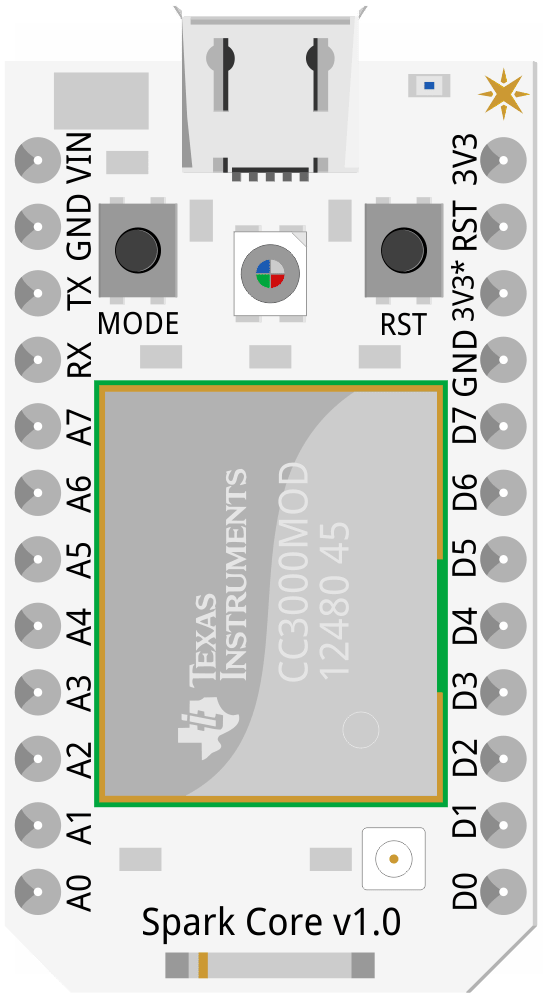
Pin Configuration and Descriptions
The SparkCore features a 20-pin layout. Below is the pin configuration:
| Pin Number | Pin Name | Description |
|---|---|---|
| 1 | VIN | Input voltage (3.6V to 6.0V) |
| 2 | GND | Ground |
| 3 | D0 | Digital I/O pin |
| 4 | D1 | Digital I/O pin |
| 5 | D2 | Digital I/O pin |
| 6 | D3 | Digital I/O pin |
| 7 | D4 | Digital I/O pin |
| 8 | D5 | Digital I/O pin |
| 9 | D6 | Digital I/O pin |
| 10 | D7 | Digital I/O pin |
| 11 | A0 | Analog input pin |
| 12 | A1 | Analog input pin |
| 13 | A2 | Analog input pin |
| 14 | A3 | Analog input pin |
| 15 | A4 | Analog input pin |
| 16 | A5 | Analog input pin |
| 17 | RX | UART receive pin |
| 18 | TX | UART transmit pin |
| 19 | RST | Reset pin |
| 20 | 3V3 | 3.3V output |
Usage Instructions
The SparkCore is designed to be user-friendly and integrates seamlessly with the Particle Cloud. Below are the steps to use the SparkCore in a circuit:
Step 1: Powering the SparkCore
- Connect the VIN pin to a power source (3.6V to 6.0V) or use a USB connection.
- Ensure the GND pin is connected to the ground of your circuit.
Step 2: Connecting to Wi-Fi
- Use the Particle mobile app or CLI to configure the Wi-Fi credentials for the SparkCore.
- Once connected, the SparkCore will automatically link to the Particle Cloud.
Step 3: Programming the SparkCore
- Write your code using the Particle Web IDE, Particle CLI, or a local development environment.
- Flash the code to the SparkCore over-the-air (OTA) via the Particle Cloud.
Step 4: Interfacing with Sensors and Actuators
- Use the digital (D0-D7) and analog (A0-A5) pins to connect sensors and actuators.
- For communication with other devices, use the UART, SPI, or I2C interfaces.
Example Code: Blinking an LED
Below is an example of how to blink an LED connected to pin D0 using the SparkCore:
// This code blinks an LED connected to pin D0 on the SparkCore

// Define the pin for the LED
int ledPin = D0;

void setup() {
  // Set the LED pin as an output
  pinMode(ledPin, OUTPUT);
}

void loop() {
  // Turn the LED on
  digitalWrite(ledPin, HIGH);
  delay(1000); // Wait for 1 second

  // Turn the LED off
  digitalWrite(ledPin, LOW);
  delay(1000); // Wait for 1 second
}
Best Practices
- Always use a stable power supply to avoid unexpected resets or malfunctions.
- Use pull-up or pull-down resistors for unused pins to prevent floating states.
- Secure your Particle Cloud account to protect your IoT devices from unauthorized access.
Troubleshooting and FAQs
Common Issues and Solutions
Issue: SparkCore is not connecting to Wi-Fi.
- Solution: Ensure the Wi-Fi credentials are correct and the network is 2.4 GHz (not 5 GHz). Reset the SparkCore and reconfigure the Wi-Fi settings using the Particle app or CLI.
Issue: Unable to flash code to the SparkCore.
- Solution: Check if the SparkCore is online in the Particle Cloud. If not, verify the power supply and Wi-Fi connection. Use the Particle CLI to manually flash the firmware.
Issue: The SparkCore is not responding to inputs/outputs.
- Solution: Ensure the pins are correctly configured in the code. Check for loose connections or damaged components.
FAQs
Q: Can the SparkCore be powered via USB?
A: Yes, the SparkCore can be powered using a standard micro-USB cable.Q: Is the SparkCore compatible with Arduino libraries?
A: Many Arduino libraries can be used with the SparkCore, but some may require modifications.Q: How do I reset the SparkCore to factory settings?
A: Hold down the MODE button for 10 seconds until the LED blinks white, then release the button.
By following this documentation, you can effectively use the SparkCore for your IoT projects. For additional support, visit the Particle community forums or refer to the official Particle documentation.