How to Use FemtoBuck LED Driver: Examples, Pinouts, and Specs
Introduction
The FemtoBuck LED Driver is a compact, high-efficiency, constant current LED driver designed to provide a stable current source for powering LEDs. It is ideal for applications requiring consistent LED brightness without fluctuations that can occur with varying voltage sources. Common applications include architectural lighting, task lighting, and DIY LED projects.
Explore Projects Built with FemtoBuck LED Driver

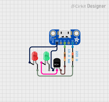
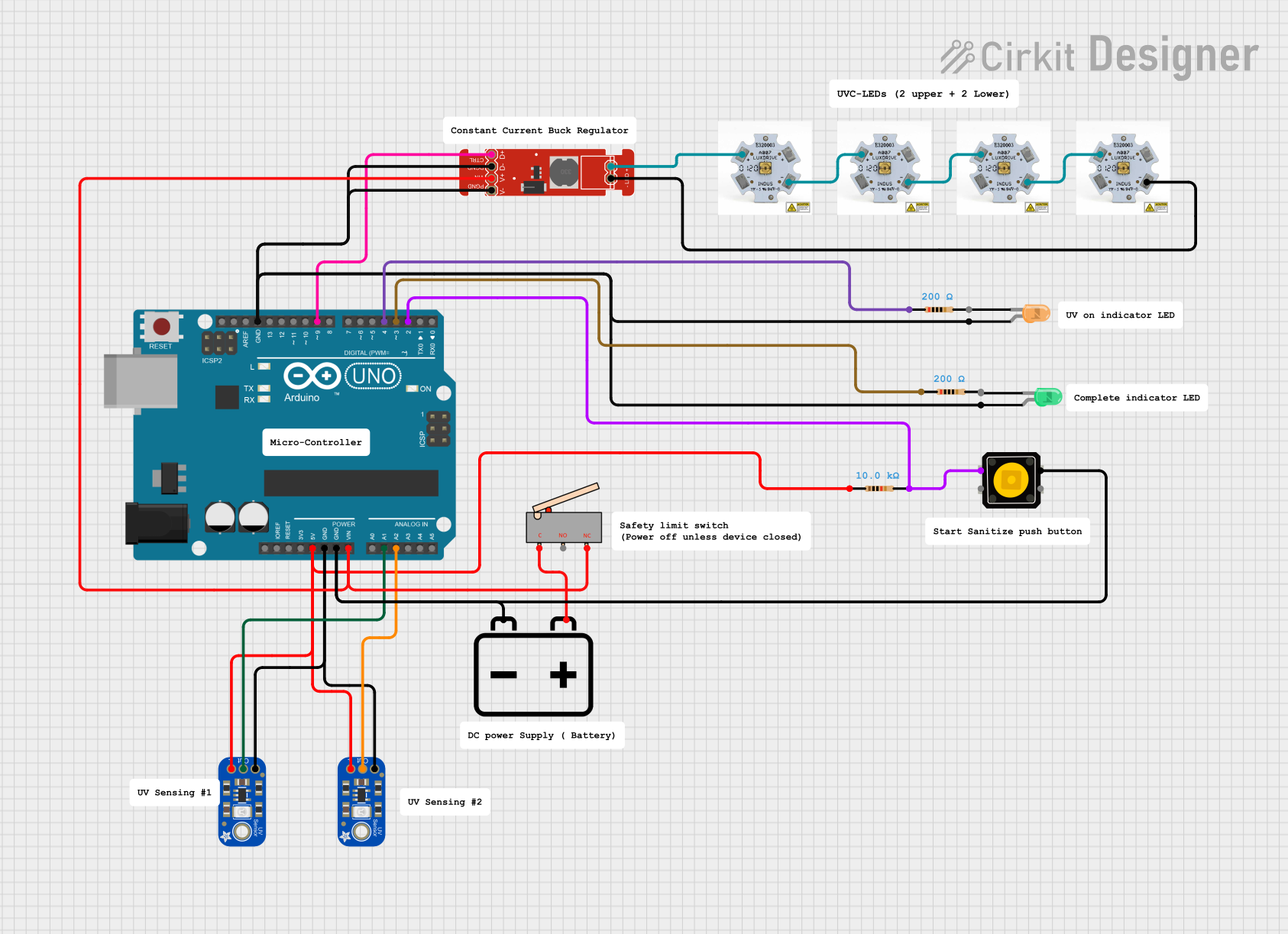
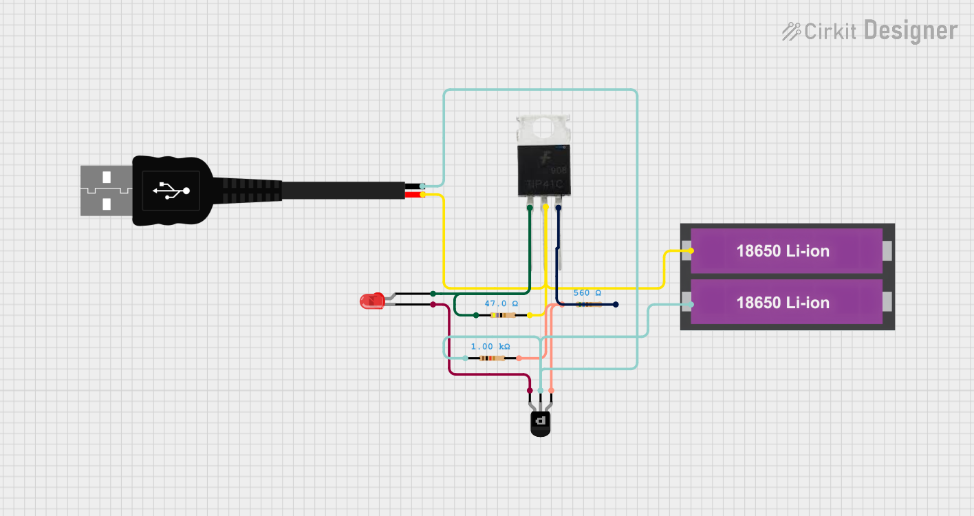
Explore Projects Built with FemtoBuck LED Driver
Technical Specifications
Key Technical Details
- Input Voltage: 6V to 36V DC
- Output Current: Adjustable up to 330mA (default set to 330mA)
- Efficiency: Up to 95%
- Dimming Control: Analog (via voltage) or PWM
- Operating Temperature: -40°C to +85°C
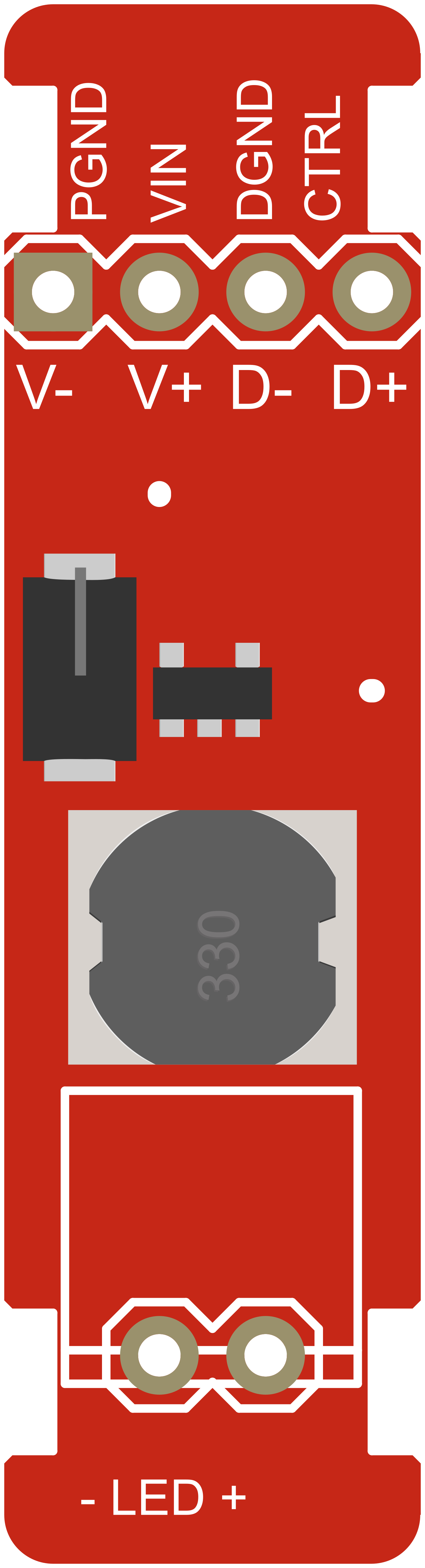
Pin Configuration and Descriptions
| Pin Number | Name | Description |
|---|---|---|
| 1 | VIN | Input voltage (6V to 36V DC) |
| 2 | GND | Ground connection |
| 3 | VOUT | LED output voltage (connected to LED anode) |
| 4 | CTRL | Dimming control input (0V to 2.5V for analog or PWM signal) |
| 5 | RSET | Sets output current (default 330mA, adjustable via external resistor) |
Usage Instructions
Connecting the FemtoBuck LED Driver
- Connect the positive terminal of your power supply to the VIN pin.
- Connect the ground of your power supply to the GND pin.
- Connect the anode of your LED to the VOUT pin.
- Connect the cathode of your LED to the ground.
- If dimming is required, connect a PWM signal or a DC voltage between 0V and 2.5V to the CTRL pin.
Important Considerations and Best Practices
- Ensure that the input voltage does not exceed 36V to prevent damage to the driver.
- Do not exceed the maximum output current of 330mA; adjust the current setting if necessary by changing the RSET resistor.
- Use proper heat sinking for the LED to prevent overheating.
- If using PWM dimming, ensure that the PWM frequency is between 100Hz and 1kHz for optimal performance.
- For analog dimming, use a high-quality, low-noise voltage source to prevent flickering.
Troubleshooting and FAQs
Common Issues
- LEDs are not lighting up: Check connections and ensure that the power supply is within the specified voltage range.
- LED brightness is fluctuating: Verify that the CTRL input is stable and not noisy. For analog dimming, use a clean voltage source.
- LEDs are too dim or too bright: Adjust the RSET resistor to calibrate the output current to the desired level.
Solutions and Tips
- Double-check all wiring connections for any loose contacts or shorts.
- Measure the input voltage and current to ensure they are within specifications.
- If using PWM dimming, verify the PWM signal with an oscilloscope to ensure it is clean and within the correct frequency range.
FAQs
Q: Can I drive multiple LEDs with one FemtoBuck LED Driver? A: Yes, as long as the total current does not exceed 330mA and the LEDs are connected in series.
Q: What is the maximum number of FemtoBuck LED Drivers I can chain together? A: There is no specific limit to the number of drivers you can chain, but power supply capacity and wiring considerations must be taken into account.
Q: How do I adjust the output current? A: The output current can be adjusted by changing the value of the RSET resistor. Please refer to the datasheet for the appropriate resistor value calculations.
Example Arduino UNO Code for PWM Dimming
// Define the PWM pin connected to the CTRL pin of the FemtoBuck
const int pwmPin = 9; // For example, using pin 9 on the Arduino UNO

void setup() {
  // Set the PWM pin as an output
  pinMode(pwmPin, OUTPUT);
}

void loop() {
  // Increase brightness
  for (int dutyCycle = 0; dutyCycle <= 255; dutyCycle++) {
    analogWrite(pwmPin, dutyCycle);
    delay(10); // Wait for 10 milliseconds
  }

  // Decrease brightness
  for (int dutyCycle = 255; dutyCycle >= 0; dutyCycle--) {
    analogWrite(pwmPin, dutyCycle);
    delay(10); // Wait for 10 milliseconds
  }
}
Note: The above code provides a simple example of how to control the brightness of an LED using the FemtoBuck LED Driver with an Arduino UNO. The analogWrite function is used to send a PWM signal to the CTRL pin of the FemtoBuck, varying the duty cycle from 0 (off) to 255 (fully on).