How to Use mlx90614: Examples, Pinouts, and Specs
Introduction
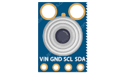
The MLX90614 is a contactless infrared (IR) temperature sensor that provides a digital output corresponding to the temperature of the object it is pointed at. This sensor is manufactured by Melexis and is designed for non-contact temperature measurements in various applications, including industrial controls, automotive systems, medical equipment, and home appliances.
Explore Projects Built with mlx90614


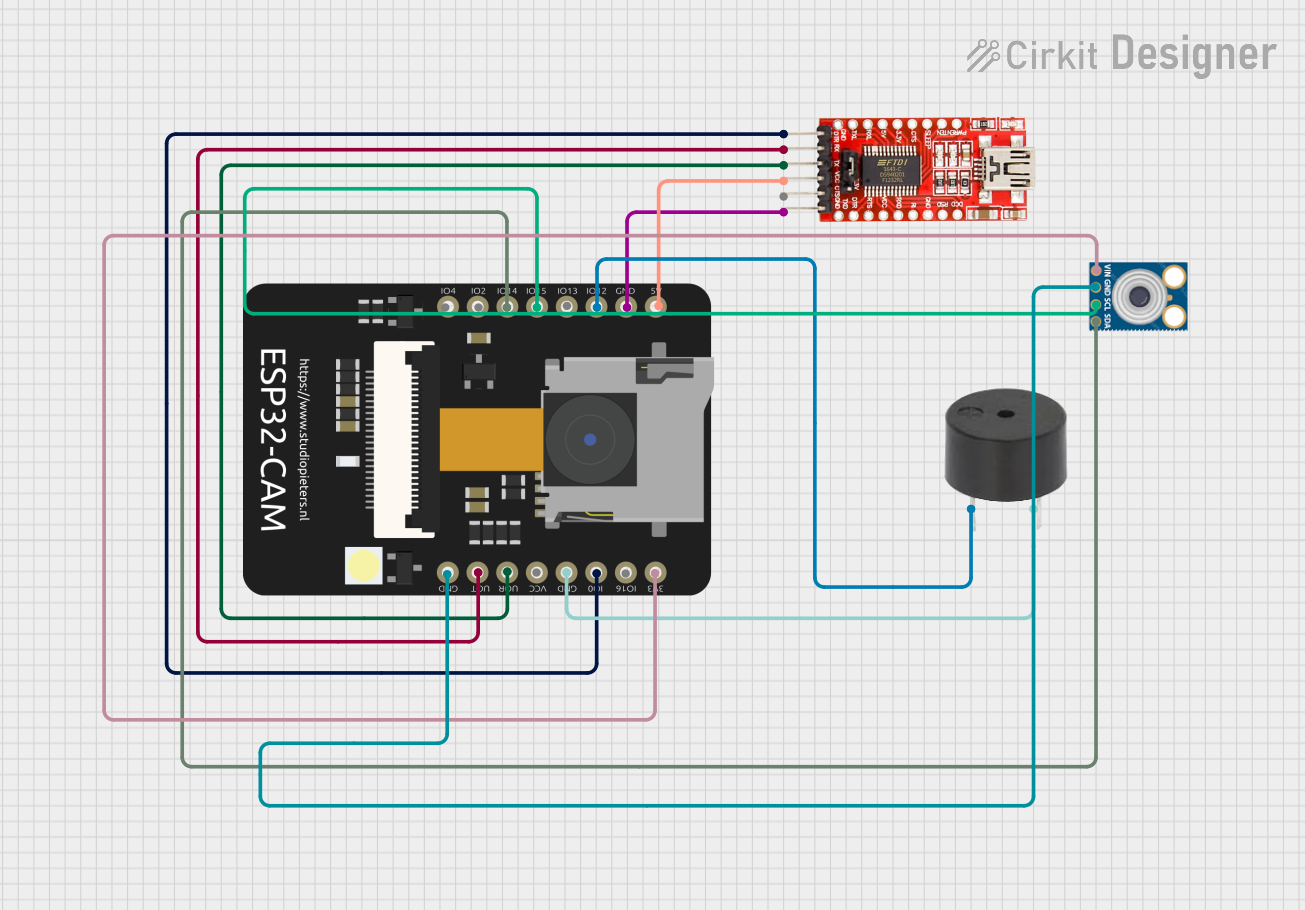
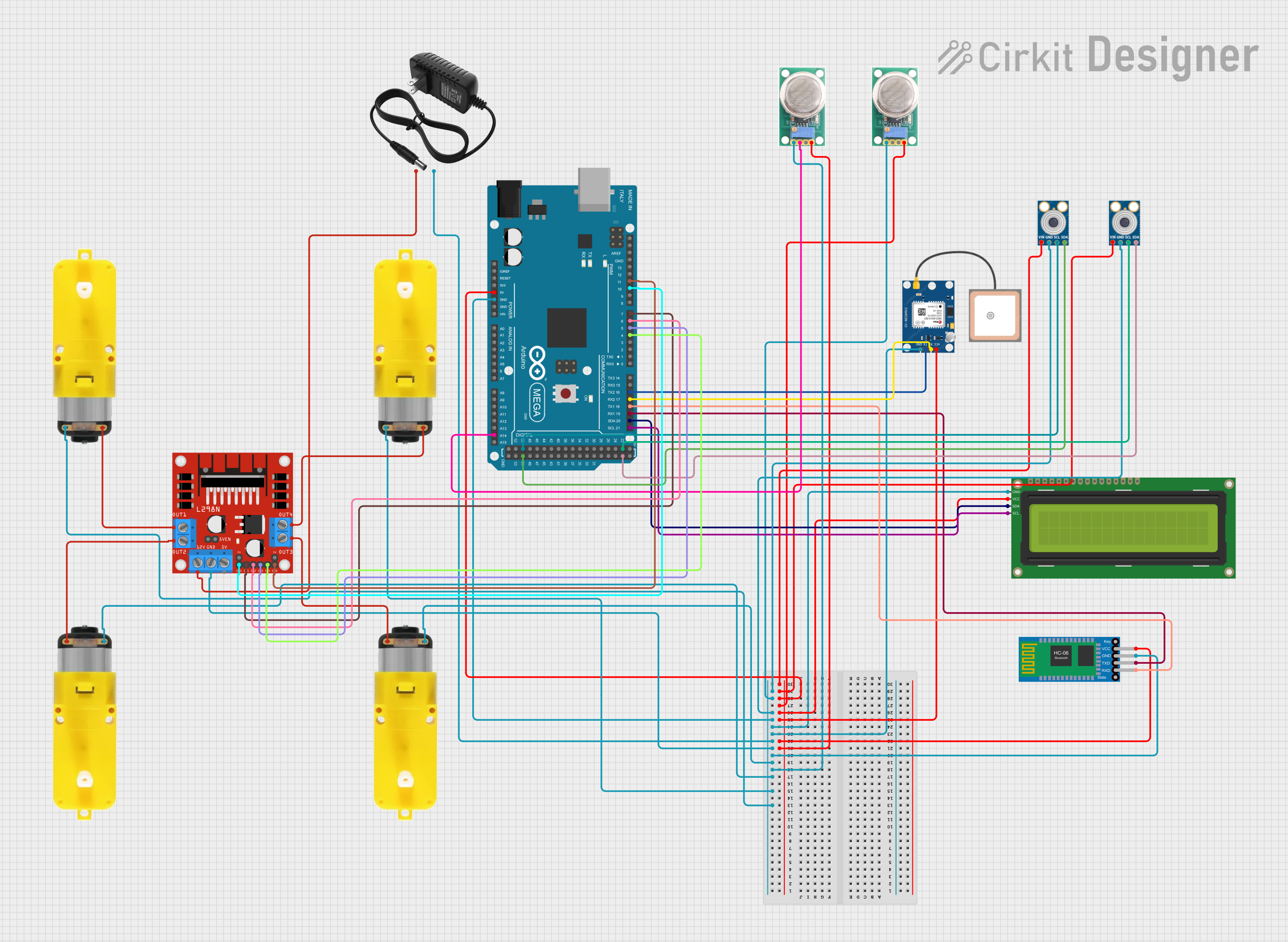
Explore Projects Built with mlx90614
Common Applications and Use Cases
- Industrial Systems: Monitoring temperatures in machinery and processes.
- Automotive: HVAC climate control and engine cooling systems.
- Medical Equipment: Non-contact thermometers for patient monitoring.
- Consumer Electronics: Home appliances like microwave ovens and cooktops.
- DIY Projects: Integration with microcontrollers like Arduino for hobbyist projects.
Technical Specifications
Key Technical Details
- Supply Voltage (Vdd): 3.3V to 5V
- Measurement Range: -70°C to +380°C for object temperature
- Field of View (FOV): 90° typical
- Resolution: 0.02°C
- Accuracy: ±0.5°C for ambient temperature; ±1°C for object temperature
- Interface: I2C-compatible digital interface
Pin Configuration and Descriptions
| Pin Number | Name | Description |
|---|---|---|
| 1 | Vdd | Power supply (3.3V to 5V) |
| 2 | SDA | I2C Data Line |
| 3 | SCL | I2C Clock Line |
| 4 | GND | Ground |
Usage Instructions
How to Use the Component in a Circuit
- Power Supply: Connect the Vdd pin to a 3.3V or 5V power supply.
- Ground: Connect the GND pin to the ground of the power supply.
- I2C Communication: Connect the SDA and SCL pins to the I2C data and clock lines of your microcontroller.
Important Considerations and Best Practices
- Power Supply: Ensure that the power supply is within the specified voltage range.
- I2C Pull-up Resistors: Typically, 4.7kΩ pull-up resistors are required on the SDA and SCL lines.
- Filtering: Place a capacitor close to the Vdd pin to filter out power supply noise.
- Field of View: Be aware of the sensor's FOV to ensure accurate temperature readings of the intended object.
- Calibration: For critical applications, calibrate the sensor in the specific environment where it will be used.
Example Code for Arduino UNO
#include <Wire.h>
#include <Adafruit_MLX90614.h>

Adafruit_MLX90614 mlx = Adafruit_MLX90614();

void setup() {
  Serial.begin(9600);
  mlx.begin();
}

void loop() {
  Serial.print("Ambient = "); Serial.print(mlx.readAmbientTempC());
  Serial.print("*C\tObject = "); Serial.print(mlx.readObjectTempC()); Serial.println("*C");
  delay(500);
}
Code Comments
#include <Wire.h>: Includes the I2C library for communication.#include <Adafruit_MLX90614.h>: Includes the library for the MLX90614 sensor.Adafruit_MLX90614 mlx: Creates an instance of the MLX90614 class.Serial.begin(9600): Initializes serial communication at 9600 baud rate.mlx.begin(): Initializes the sensor.mlx.readAmbientTempC(): Reads the ambient temperature in Celsius.mlx.readObjectTempC(): Reads the object temperature in Celsius.delay(500): Pauses the loop for 500 milliseconds.
Troubleshooting and FAQs
Common Issues
- Inaccurate Readings: Ensure that the sensor is not exposed to sudden temperature changes and that the FOV is correctly aligned with the target.
- No Data on I2C: Check the wiring, ensure pull-up resistors are installed, and verify that the correct I2C address is being used.
Solutions and Tips for Troubleshooting
- Power Supply Issues: Verify that the power supply is stable and within the specified voltage range.
- I2C Communication: Use an I2C scanner sketch to confirm that the sensor is detected on the I2C bus.
- Sensor Placement: Adjust the sensor's position to avoid interference from surrounding objects.
FAQs
Q: Can the MLX90614 measure the temperature through glass? A: No, the sensor cannot measure through glass as it blocks IR radiation.
Q: Is the MLX90614 waterproof? A: The sensor itself is not waterproof. It requires additional protection if used in a moist environment.
Q: How can I calibrate the MLX90614? A: Calibration should be done against a known temperature reference in the same environmental conditions as the intended application.
Q: What is the I2C address of the MLX90614? A: The default I2C address is 0x5A. However, it can vary with different versions of the sensor.
This documentation provides a comprehensive guide to the MLX90614 IR temperature sensor, ensuring users can effectively integrate and utilize this component in their projects.