
How to Use Shunt 500A: Examples, Pinouts, and Specs
 Design with Shunt 500A in Cirkit Designer
Introduction
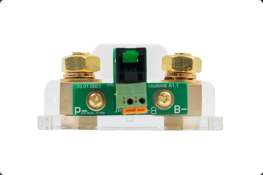
The Shunt 500A by Kings is a precision low-resistance component designed for current measurement in high-power systems. It operates by generating a small, proportional voltage drop across its terminals when current flows through it. This voltage drop can then be measured and used to calculate the current. The 500A rating indicates that the shunt can handle a maximum current of 500 amperes without damage or loss of accuracy.
Explore Projects Built with Shunt 500A
 Open Project in Cirkit Designer
 Open Project in Cirkit Designer
 Open Project in Cirkit Designer
 Open Project in Cirkit Designer
Explore Projects Built with Shunt 500A
Open Project in Cirkit DesignerOpen Project in Cirkit DesignerOpen Project in Cirkit DesignerOpen Project in Cirkit DesignerCommon Applications and Use Cases
- Battery management systems (BMS) for electric vehicles and renewable energy setups
- High-current DC power supplies and monitoring systems
- Industrial equipment and machinery current measurement
- Integration with microcontrollers or data acquisition systems for real-time current monitoring
Technical Specifications
The following table outlines the key technical details of the Shunt 500A:
| Parameter | Value |
|---|---|
| Maximum Current Rating | 500A |
| Resistance Value | Typically 50 µΩ (micro-ohms) |
| Voltage Drop (at 500A) | 50 mV |
| Accuracy | ±0.5% |
| Operating Temperature | -40°C to +85°C |
| Material | Manganin (high-stability alloy) |
| Dimensions | 120mm x 25mm x 15mm |
| Mounting Style | Bolt-on |
Pin Configuration and Descriptions
The Shunt 500A does not have traditional pins but instead features two main terminals for current flow and two smaller terminals for voltage sensing. The configuration is as follows:
| Terminal | Description |
|---|---|
| Current Terminal 1 | Connects to the positive side of the current path. |
| Current Terminal 2 | Connects to the negative side of the current path. |
| Sense Terminal 1 | Voltage sensing terminal for measuring the voltage drop across the shunt. |
| Sense Terminal 2 | Voltage sensing terminal for measuring the voltage drop across the shunt. |
Usage Instructions
How to Use the Shunt 500A in a Circuit
Placement in the Circuit:
- Place the shunt in series with the load whose current you want to measure.
- Ensure the current terminals are securely bolted to the circuit to handle high currents.
Voltage Sensing:
- Connect the sense terminals to a high-impedance voltmeter, ADC (Analog-to-Digital Converter), or microcontroller input.
- The voltage drop across the sense terminals will be proportional to the current flowing through the shunt.
Current Calculation:
- Use Ohm's Law to calculate the current:
[ I = \frac{V}{R} ]
Where (I) is the current, (V) is the measured voltage drop, and (R) is the shunt resistance (50 µΩ).
- Use Ohm's Law to calculate the current:
Power Dissipation:
- Ensure the power dissipation ((P = I^2 \times R)) does not exceed the shunt's thermal limits.
Important Considerations and Best Practices
- Thermal Management: The shunt may heat up under high current. Ensure adequate ventilation or cooling if necessary.
- Voltage Measurement Accuracy: Use a high-precision voltmeter or ADC to minimize measurement errors.
- Wiring: Use thick, low-resistance wires for the current terminals to avoid additional resistance in the circuit.
- Polarity: Ensure correct polarity when connecting the shunt to avoid incorrect readings or damage.
Example: Connecting to an Arduino UNO
The Shunt 500A can be used with an Arduino UNO to measure high currents. Below is an example setup and code:
Circuit Setup
- Connect the shunt's sense terminals to the Arduino's analog input pins (e.g., A0 and GND).
- Use a voltage divider if the voltage drop exceeds the Arduino's ADC input range (0-5V).
- Power the Arduino and ensure the shunt is properly connected in the circuit.
Arduino Code
// Define constants
const float shuntResistance = 0.00005; // Shunt resistance in ohms (50 µΩ)
const float adcReferenceVoltage = 5.0; // Arduino ADC reference voltage
const int adcResolution = 1024;        // ADC resolution (10-bit)

// Analog pin for voltage measurement
const int voltagePin = A0;

void setup() {
  Serial.begin(9600); // Initialize serial communication
}

void loop() {
  // Read the analog voltage
  int adcValue = analogRead(voltagePin);

  // Convert ADC value to voltage
  float measuredVoltage = (adcValue * adcReferenceVoltage) / adcResolution;

  // Calculate current using Ohm's Law
  float current = measuredVoltage / shuntResistance;

  // Print the current to the Serial Monitor
  Serial.print("Current: ");
  Serial.print(current);
  Serial.println(" A");

  delay(1000); // Wait for 1 second before the next reading
}
Troubleshooting and FAQs
Common Issues Users Might Face
Inaccurate Current Readings:
- Cause: Poor connections at the current or sense terminals.
- Solution: Ensure all connections are tight and use appropriate wiring.
Overheating:
- Cause: Exceeding the shunt's maximum current rating or poor ventilation.
- Solution: Reduce the current or improve cooling around the shunt.
No Voltage Drop Detected:
- Cause: Incorrect wiring or damaged sense terminals.
- Solution: Verify the wiring and check the shunt for physical damage.
Arduino ADC Saturation:
- Cause: Voltage drop exceeds the ADC input range.
- Solution: Use a voltage divider or external ADC with a higher input range.
FAQs
Q1: Can the Shunt 500A be used for AC current measurement?
A1: No, the shunt is designed for DC current measurement. For AC, use a current transformer or hall-effect sensor.
Q2: What happens if the current exceeds 500A?
A2: Exceeding the maximum current rating can cause overheating, damage, or loss of accuracy. Always stay within the rated limits.
Q3: How do I ensure accurate measurements?
A3: Use a high-precision voltmeter or ADC, minimize noise in the circuit, and ensure proper wiring.
Q4: Can I use the shunt with other microcontrollers?
A4: Yes, the shunt can be used with any microcontroller that has an ADC input, such as ESP32, STM32, or Raspberry Pi (with an external ADC).