How to Use 8051: Examples, Pinouts, and Specs
Introduction
The 8051 is a widely used microcontroller developed by Intel and manufactured by various companies, including Microcontroller. It features an 8-bit CPU, 4 KB of ROM, 128 bytes of RAM, and multiple I/O ports, making it a versatile choice for embedded systems. The 8051 is known for its simplicity, reliability, and extensive support in the embedded systems community.
Explore Projects Built with 8051
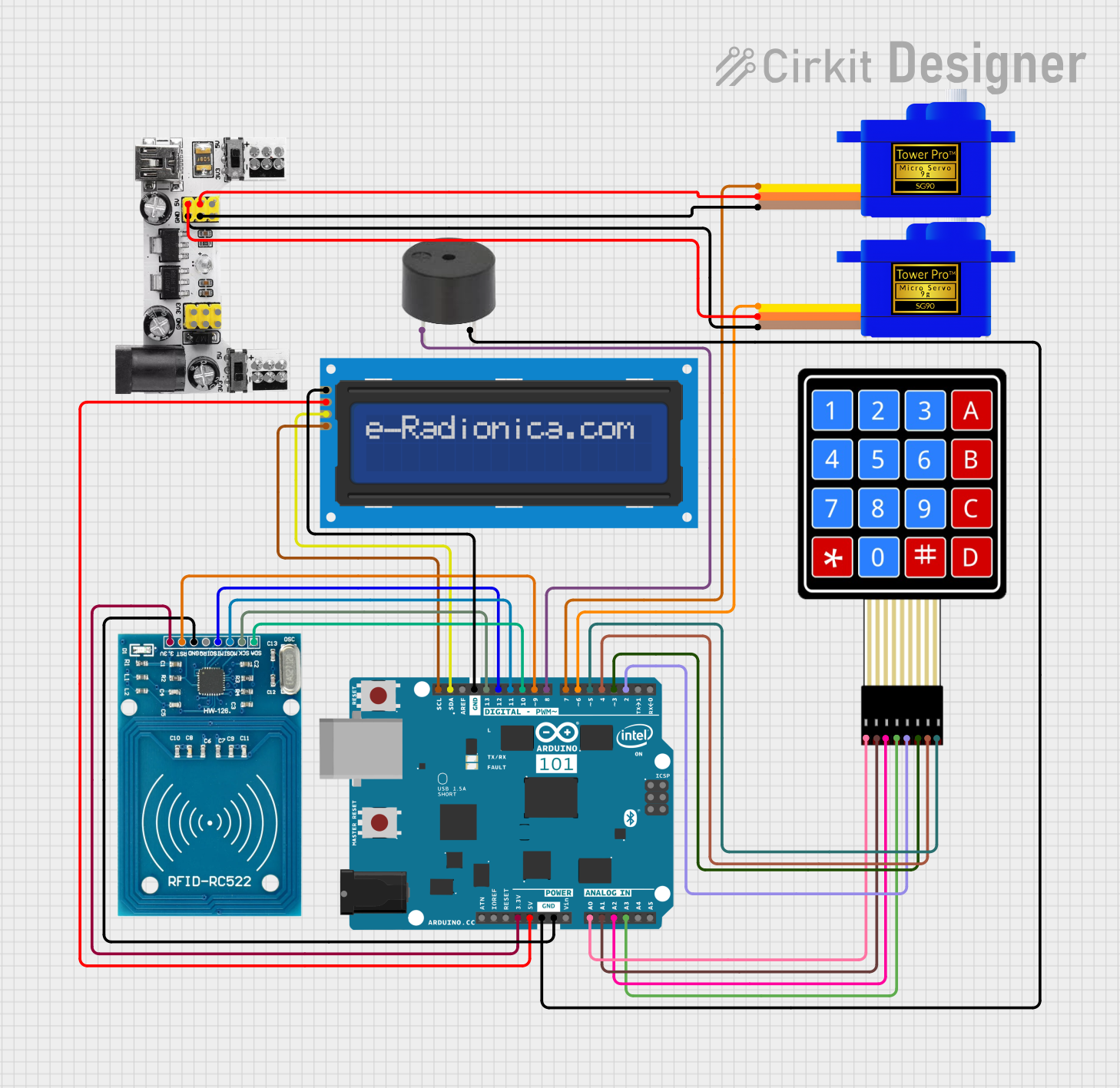
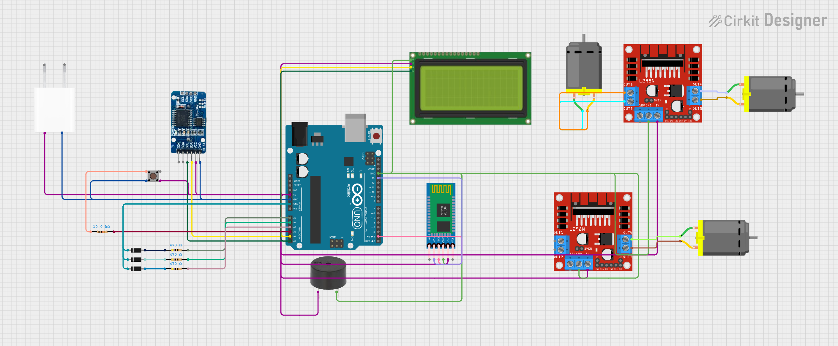
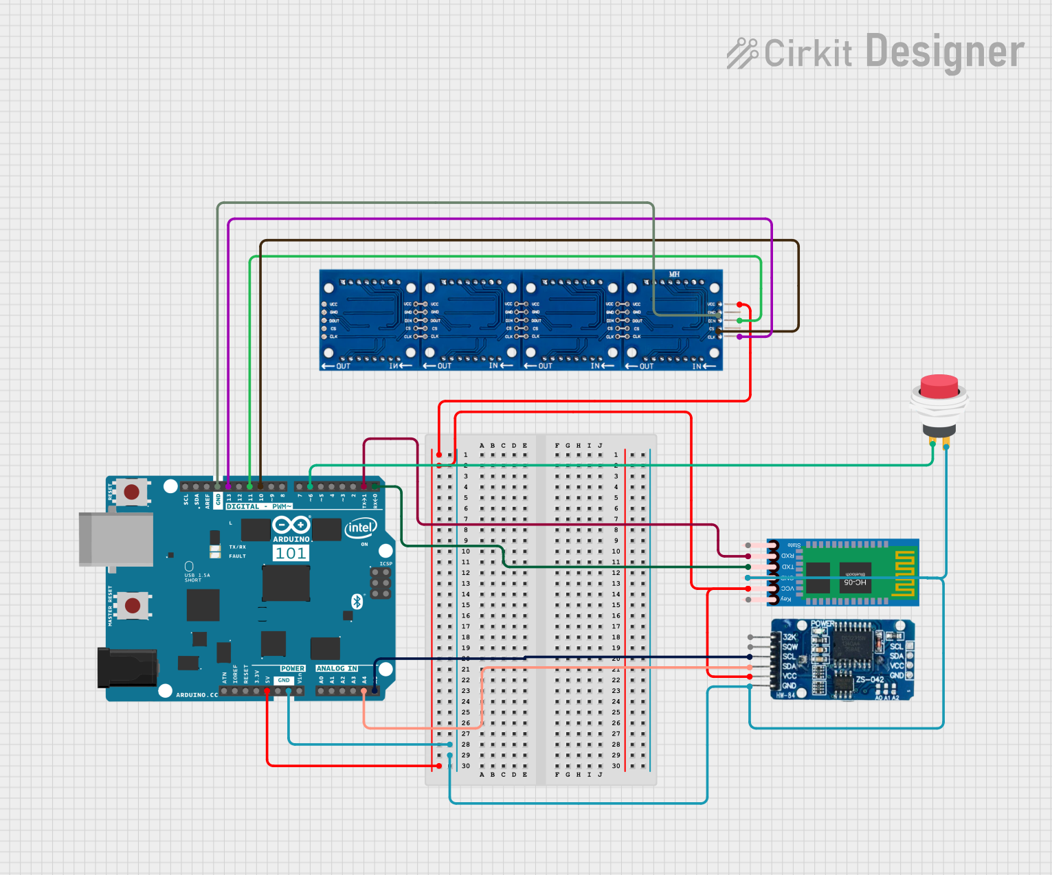
Explore Projects Built with 8051
Common Applications and Use Cases
- Home automation systems
- Industrial control systems
- Consumer electronics
- Data acquisition systems
- Robotics and motor control
- Communication devices
Technical Specifications
The 8051 microcontroller is designed to meet the needs of a wide range of embedded applications. Below are its key technical details:
Key Technical Details
- CPU Architecture: 8-bit
- ROM: 4 KB (on-chip, mask-programmable)
- RAM: 128 bytes (on-chip)
- Clock Speed: Up to 12 MHz
- I/O Ports: 4 (each 8-bit wide)
- Timers/Counters: 2 (16-bit each)
- Interrupts: 5 sources, 2 priority levels
- Serial Communication: Full-duplex UART
- Power Supply Voltage: 4.0V to 5.5V
- Operating Temperature: -40°C to +85°C
Pin Configuration and Descriptions
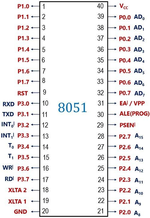
The 8051 microcontroller is typically available in a 40-pin DIP (Dual Inline Package). Below is the pin configuration and description:
| Pin Number | Pin Name | Description |
|---|---|---|
| 1-8 | P1.0-P1.7 | Port 1: 8-bit bidirectional I/O port |
| 9 | RST | Reset: Active high input to reset the microcontroller |
| 10-17 | P3.0-P3.7 | Port 3: 8-bit bidirectional I/O port with alternate functions (e.g., UART, INT) |
| 18-19 | XTAL2, XTAL1 | Crystal oscillator pins for external clock input |
| 20 | GND | Ground |
| 21-28 | P2.0-P2.7 | Port 2: 8-bit bidirectional I/O port |
| 29 | PSEN | Program Store Enable: Used to read external program memory |
| 30 | ALE | Address Latch Enable: Used for external memory interfacing |
| 31 | EA | External Access: Enables/disables external memory |
| 32-39 | P0.0-P0.7 | Port 0: 8-bit bidirectional I/O port (also used for address/data bus) |
| 40 | VCC | Power supply (4.0V to 5.5V) |
Usage Instructions
The 8051 microcontroller is straightforward to use in embedded systems. Below are the steps and best practices for integrating it into a circuit:
How to Use the 8051 in a Circuit
- Power Supply: Connect the VCC pin to a 5V power source and the GND pin to ground.
- Clock Configuration: Attach a crystal oscillator (typically 12 MHz) between XTAL1 and XTAL2, along with two 33pF capacitors to ground.
- Reset Circuit: Connect a push-button and a pull-up resistor to the RST pin for manual reset functionality.
- I/O Ports: Use the I/O ports (P0, P1, P2, P3) for interfacing with external devices such as LEDs, sensors, or motors.
- External Memory (if needed): If your application requires more memory, connect external ROM or RAM using the PSEN, ALE, and EA pins.
Important Considerations and Best Practices
- Decoupling Capacitors: Place decoupling capacitors (e.g., 0.1 µF) near the power pins to reduce noise.
- Pull-up Resistors: Use pull-up resistors on Port 0 if it is used as a general-purpose I/O port.
- Programming: Use an 8051-compatible programmer to load your code into the microcontroller.
- Code Optimization: Optimize your code to fit within the 4 KB ROM and 128 bytes of RAM.
Example Code for Arduino UNO Integration
The 8051 can communicate with an Arduino UNO via UART. Below is an example of how to send data from the Arduino to the 8051:
// Arduino UNO Code: Sending data to 8051 via UART
void setup() {
  Serial.begin(9600); // Initialize UART communication at 9600 baud rate
}

void loop() {
  Serial.println("Hello, 8051!"); // Send a message to the 8051
  delay(1000); // Wait for 1 second
}
On the 8051 side, configure the UART to receive data at 9600 baud and process the incoming data accordingly.
Troubleshooting and FAQs
Common Issues and Solutions
Microcontroller Not Responding
- Cause: Incorrect power supply or clock configuration.
- Solution: Verify the power supply voltage (4.0V to 5.5V) and ensure the crystal oscillator is properly connected.
I/O Ports Not Functioning
- Cause: Missing pull-up resistors on Port 0 or incorrect pin configuration.
- Solution: Add pull-up resistors to Port 0 and check the pin configuration in your code.
Program Not Running
- Cause: Improper reset circuit or programming error.
- Solution: Check the reset circuit and reprogram the microcontroller with verified code.
Serial Communication Issues
- Cause: Mismatched baud rate or incorrect wiring.
- Solution: Ensure the baud rate matches on both devices and verify the TX/RX connections.
FAQs
Q1: Can the 8051 interface with modern sensors?
A1: Yes, the 8051 can interface with modern sensors using I2C, SPI, or UART protocols, but additional interfacing ICs may be required.
Q2: How do I expand the memory of the 8051?
A2: Use external ROM or RAM chips and connect them to the microcontroller via the PSEN, ALE, and EA pins.
Q3: Is the 8051 suitable for low-power applications?
A3: Yes, the 8051 supports power-saving modes, making it suitable for low-power applications.
Q4: Can I program the 8051 in C?
A4: Yes, the 8051 can be programmed in C using compilers like Keil µVision or SDCC.
By following this documentation, you can effectively integrate and troubleshoot the 8051 microcontroller in your embedded projects.