How to Use Ethernet Smooth Stepper: Examples, Pinouts, and Specs
Introduction
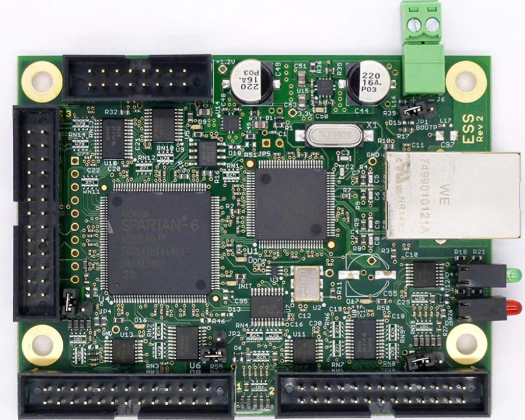
The Ethernet Smooth Stepper (ESS) by Warp9 is a high-performance motion control device designed to interface with CNC machines. It connects to a computer via Ethernet, providing precise and smooth motion control. The ESS is ideal for applications requiring high precision, such as CNC milling, 3D printing, and other automated machinery.
Explore Projects Built with Ethernet Smooth Stepper
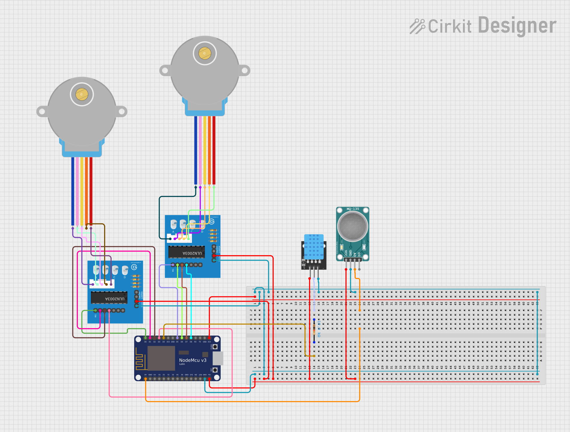
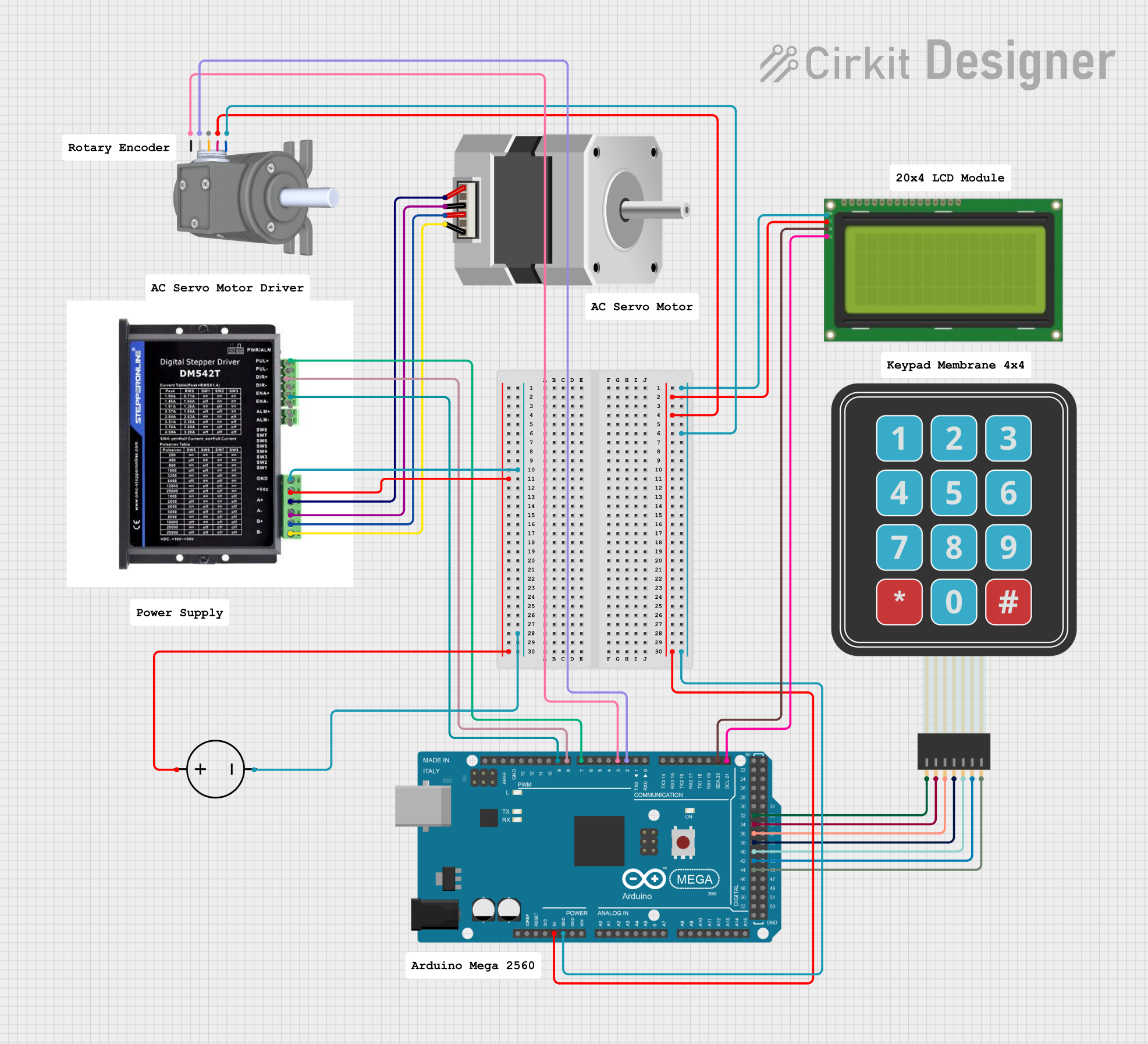
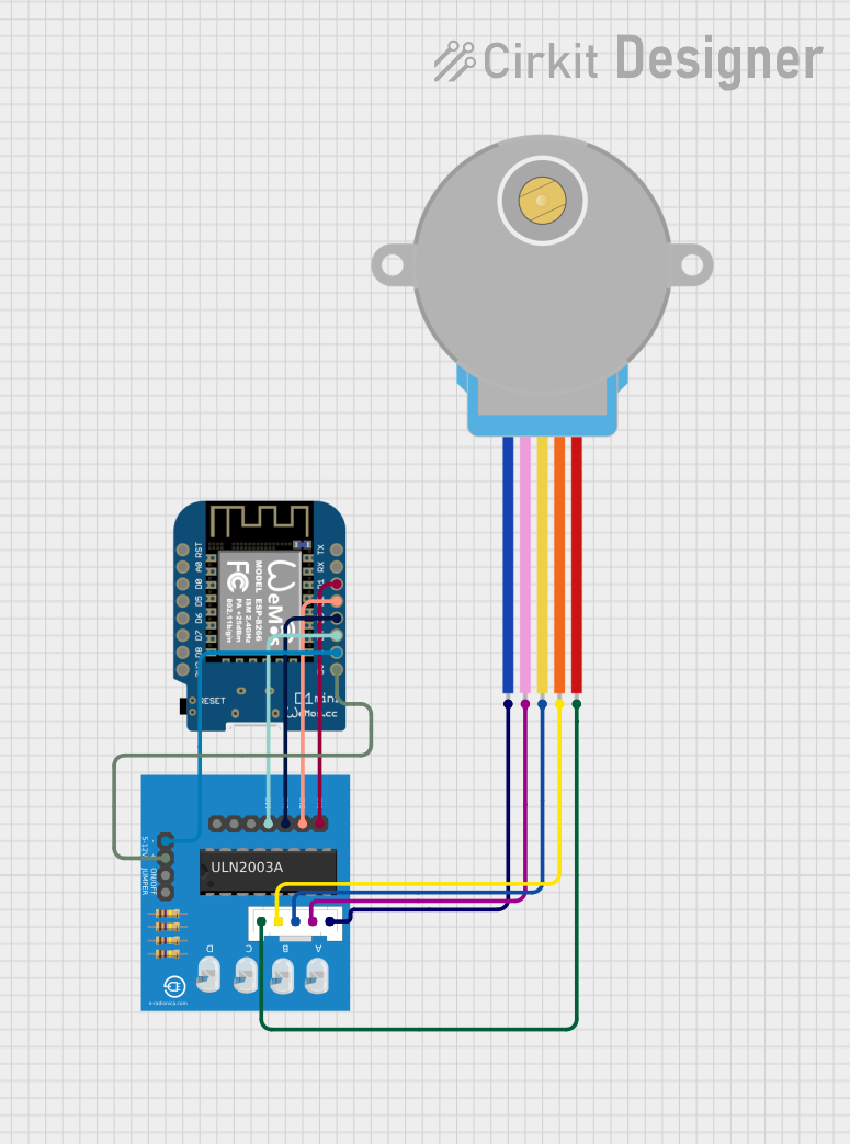
Explore Projects Built with Ethernet Smooth Stepper
Technical Specifications
Key Technical Details
| Specification | Value |
|---|---|
| Manufacturer | Warp9 |
| Part ID | ESS |
| Communication | Ethernet |
| Power Supply | 5V DC |
| Current Consumption | 500mA |
| Step Pulse Rate | Up to 4 MHz |
| Number of Axes | 6 |
| Input Voltage Range | 3.3V to 5V (for I/O pins) |
| Operating Temperature | 0°C to 70°C |
Pin Configuration and Descriptions
| Pin Number | Pin Name | Description |
|---|---|---|
| 1 | GND | Ground |
| 2 | 5V | 5V Power Supply |
| 3 | TX+ | Ethernet Transmit Positive |
| 4 | TX- | Ethernet Transmit Negative |
| 5 | RX+ | Ethernet Receive Positive |
| 6 | RX- | Ethernet Receive Negative |
| 7-12 | IO1-IO6 | General Purpose Input/Output Pins |
| 13-18 | STEP1-STEP6 | Step Signal Outputs for Axes 1 to 6 |
| 19-24 | DIR1-DIR6 | Direction Signal Outputs for Axes 1 to 6 |
| 25-30 | EN1-EN6 | Enable Signal Outputs for Axes 1 to 6 |
Usage Instructions
How to Use the ESS in a Circuit
- Power Supply: Connect the 5V power supply to the 5V pin and ground to the GND pin.
- Ethernet Connection: Connect the Ethernet cable to the TX+/- and RX+/- pins to establish communication with the computer.
- Connecting to CNC Machine:
- Connect the STEP and DIR pins to the corresponding stepper motor drivers.
- Connect the EN pins to enable the stepper motor drivers.
- I/O Pins: Use the IO pins for additional inputs and outputs as needed.
Important Considerations and Best Practices
- Power Supply: Ensure a stable 5V power supply to avoid damage to the ESS.
- Ethernet Cable: Use a high-quality Ethernet cable to ensure reliable communication.
- Shielding: Properly shield the ESS and cables to minimize electromagnetic interference.
- Cooling: Ensure adequate cooling if the ESS is used in a high-temperature environment.
Troubleshooting and FAQs
Common Issues and Solutions
No Communication with Computer:
- Solution: Check the Ethernet cable and connections. Ensure the computer's network settings are configured correctly.
Stepper Motors Not Moving:
- Solution: Verify the connections to the stepper motor drivers. Check the power supply and ensure the enable signals are correctly configured.
Erratic Motion:
- Solution: Check for electromagnetic interference. Ensure proper grounding and shielding of the ESS and cables.
FAQs
Q1: Can the ESS be used with an Arduino UNO?
- A1: Yes, the ESS can be interfaced with an Arduino UNO using the Ethernet shield. Below is an example code to send commands from Arduino to ESS:
#include <SPI.h>
#include <Ethernet.h>

// MAC address and IP address for the Ethernet shield
byte mac[] = { 0xDE, 0xAD, 0xBE, 0xEF, 0xFE, 0xED };
IPAddress ip(192.168.1.177);
IPAddress essIp(192.168.1.100); // IP address of the ESS
EthernetClient client;

void setup() {
  // Start the Ethernet connection
  Ethernet.begin(mac, ip);
  Serial.begin(9600);

  // Give the Ethernet shield a second to initialize
  delay(1000);

  // Connect to the ESS
  if (client.connect(essIp, 23)) {
    Serial.println("Connected to ESS");
  } else {
    Serial.println("Connection to ESS failed");
  }
}

void loop() {
  // Example command to move axis 1
  if (client.connected()) {
    client.println("G01 X10 F100"); // G-code command to move X axis
    delay(1000);
  } else {
    Serial.println("Disconnected from ESS");
  }
}
Q2: What is the maximum step pulse rate of the ESS?
- A2: The ESS supports a maximum step pulse rate of up to 4 MHz.
Q3: Can the ESS control more than 6 axes?
- A3: No, the ESS is designed to control up to 6 axes.
Q4: What is the input voltage range for the I/O pins?
- A4: The input voltage range for the I/O pins is 3.3V to 5V.
By following this documentation, users can effectively utilize the Ethernet Smooth Stepper (ESS) for their CNC machine control applications, ensuring smooth and precise motion control.