How to Use oled display 2.42: Examples, Pinouts, and Specs
Introduction
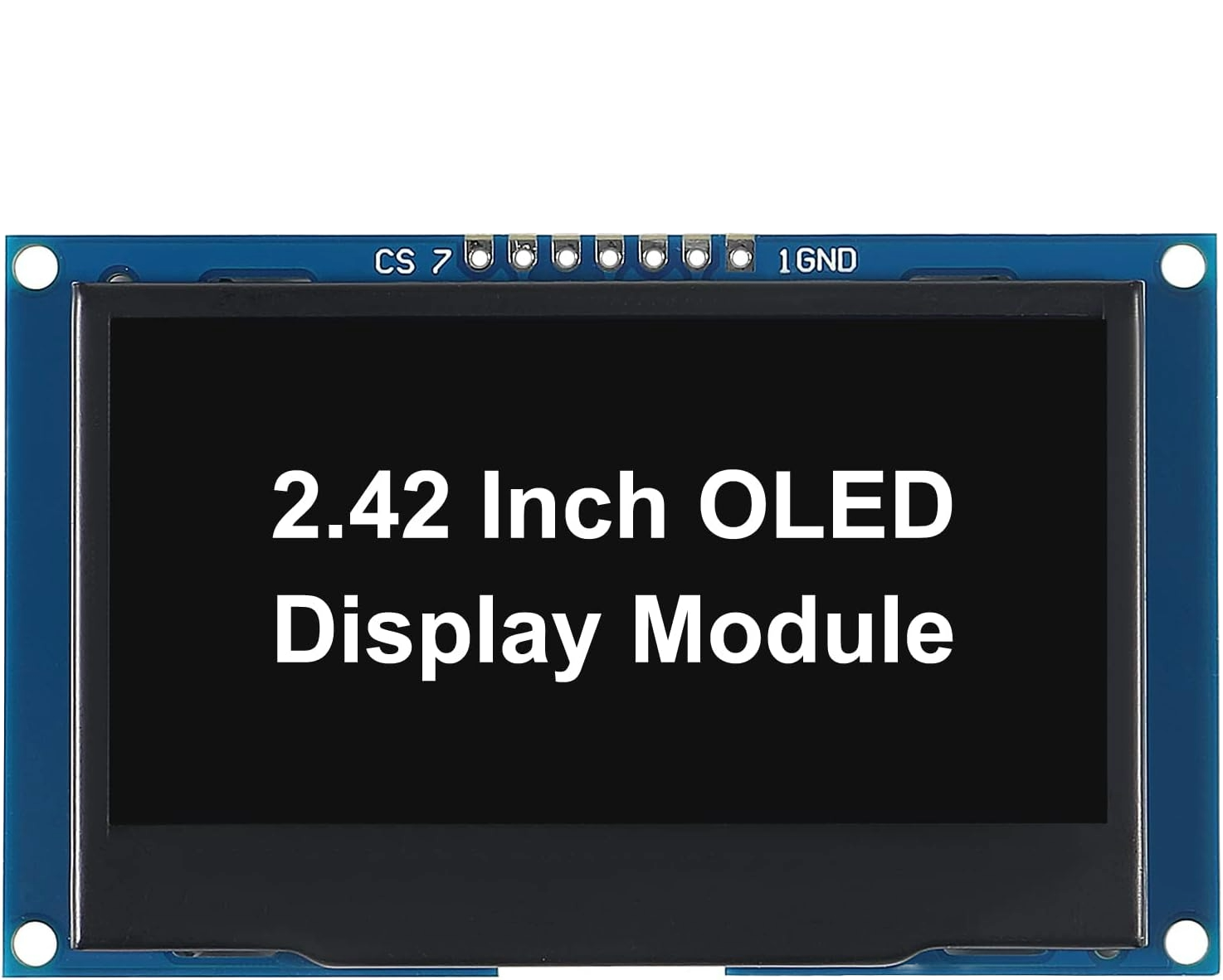
The OLED Display 2.42" is an Organic Light Emitting Diode display module that offers high contrast and brightness, making it ideal for a wide range of applications. This display technology is known for its ability to produce true blacks, as each pixel emits its own light, allowing for a very thin and energy-efficient design. Common applications include user interfaces, digital signage, personal electronics, and any application where visual output is required.
Explore Projects Built with oled display 2.42


Explore Projects Built with oled display 2.42
Technical Specifications
Key Technical Details
- Screen Size: 2.42 inches
- Resolution: 128x64 pixels
- Color Depth: Monochrome
- Interface: I2C/SPI (model-specific)
- Operating Voltage: 3.3V - 5V
- Current Consumption: Typically 20mA (varies with brightness)
- Viewing Angle: >160 degrees
Pin Configuration and Descriptions
| Pin Number | Pin Name | Description |
|---|---|---|
| 1 | GND | Ground |
| 2 | VCC | Power supply (3.3V - 5V) |
| 3 | SCL | Serial Clock Line (I2C) or SPI Clock (SPI) |
| 4 | SDA | Serial Data Line (I2C) or SPI Data In (SPI) |
| 5 | RES | Reset pin, active low |
| 6 | DC | Data/Command control pin (SPI only) |
| 7 | CS | Chip Select (SPI only) |
Note: The pin configuration may vary slightly depending on the manufacturer. Always consult the datasheet of the specific model you are using.
Usage Instructions
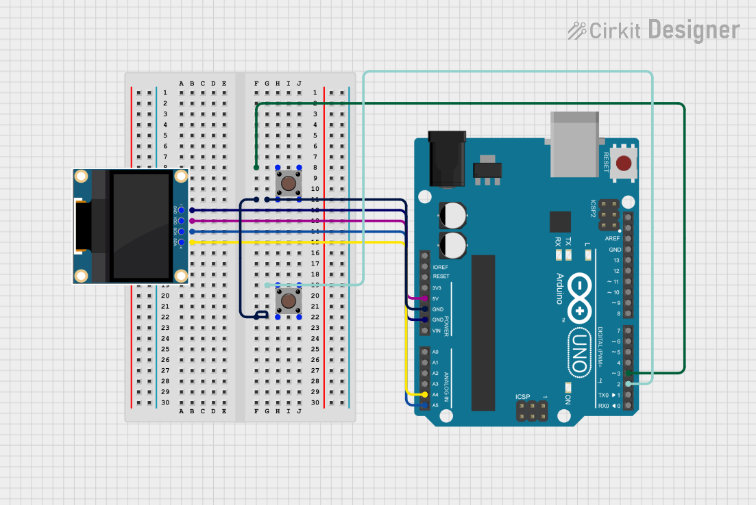
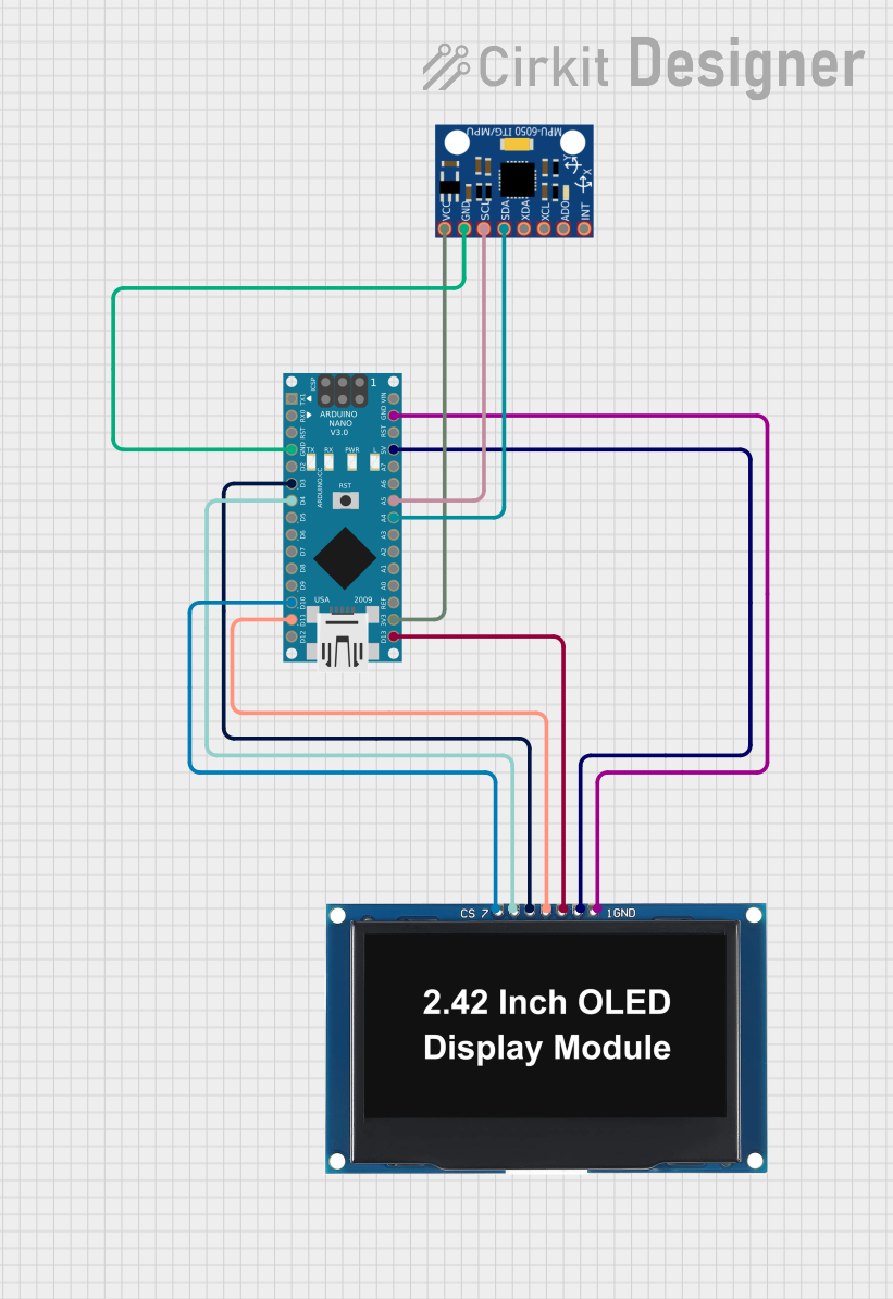
Integration with a Circuit
To use the OLED Display 2.42" in a circuit:
- Connect the GND pin to the ground of your power supply.
- Connect the VCC pin to a 3.3V or 5V power supply.
- For I2C communication, connect the SCL and SDA pins to the corresponding I2C clock and data lines on your microcontroller.
- For SPI communication, additionally connect the RES, DC, and CS pins to available digital pins on your microcontroller.
Best Practices
- Use a level shifter if your microcontroller operates at a different logic level than the display.
- Implement proper power management to avoid excessive current draw.
- Avoid exposing the display to direct sunlight or high temperatures to prevent damage.
Example Code for Arduino UNO
#include <Wire.h> // Include Wire library for I2C
#include <Adafruit_GFX.h> // Include core graphics library
#include <Adafruit_SSD1306.h> // Include Adafruit SSD1306 library to drive the display

// OLED display TWI address (check datasheet for the address)
#define OLED_ADDR   0x3C
// Reset pin not used but required for library
#define OLED_RESET  -1
Adafruit_SSD1306 display(128, 64, &Wire, OLED_RESET);

void setup() {
  // Initialize with the I2C addr 0x3C (for the 128x64)
  if(!display.begin(SSD1306_SWITCHCAPVCC, OLED_ADDR)) {
    Serial.println(F("SSD1306 allocation failed"));
    for(;;); // Don't proceed, loop forever
  }
  display.display(); // Show initial display buffer contents on the screen
  delay(2000); // Pause for 2 seconds
  display.clearDisplay(); // Clear the buffer
}

void loop() {
  display.setTextSize(1); // Normal 1:1 pixel scale
  display.setTextColor(SSD1306_WHITE); // Draw white text
  display.setCursor(0,0); // Start at top-left corner
  display.println(F("Hello, World!"));

  display.display(); // Update screen with each newly-drawn buffer
  delay(2000); // Pause for 2 seconds
}
Note: The above code assumes the use of the Adafruit SSD1306 library and GFX library. Make sure to install these libraries through the Arduino Library Manager before compiling.
Troubleshooting and FAQs
Common Issues
- Display not powering on: Check the power connections and ensure the voltage is within the specified range.
- No text or graphics appearing: Verify that the I2C/SPI connections are correct and that the correct communication protocol is selected in the code.
- Garbled or incorrect display output: Ensure that the display's resolution in the code matches the actual resolution of your OLED module.
Solutions and Tips
- Double-check wiring against the datasheet.
- Use the
display.display()function to refresh the screen after drawing operations. - Reset the display if experiencing continuous issues.
FAQs
Q: Can the display be used with 5V logic? A: Yes, but a level shifter is recommended for safe operation with 5V logic microcontrollers.
Q: How can I display images on the OLED?
A: Convert images to a bitmap array and use the display.drawBitmap() function provided by the Adafruit GFX library.
Q: Is it possible to use multiple OLED displays with an Arduino? A: Yes, if using I2C, each display must have a unique address. For SPI, use separate CS pins for each display.
For further assistance, consult the community forums or the manufacturer's technical support.