How to Use USB to Multi-Protocol Serial Cable: Examples, Pinouts, and Specs
Introduction
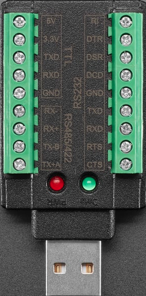
The Adafruit USB to Multi-Protocol Serial Cable (Part ID: RS-232 / TTL UART / RS-485) is a versatile tool designed to bridge USB ports with devices that use various serial communication protocols. This cable supports RS-232, TTL UART, and RS-485 standards, making it an essential component for interfacing with legacy systems, industrial equipment, and microcontrollers. It simplifies data transfer and device control by providing a plug-and-play solution for serial communication.
Explore Projects Built with USB to Multi-Protocol Serial Cable


Explore Projects Built with USB to Multi-Protocol Serial Cable
Common Applications and Use Cases
- Interfacing with industrial equipment using RS-485 or RS-232 protocols.
- Debugging and programming microcontrollers via TTL UART.
- Connecting legacy serial devices to modern computers via USB.
- Data logging and communication in embedded systems.
- Prototyping and testing serial communication protocols.
Technical Specifications
The following table outlines the key technical details of the USB to Multi-Protocol Serial Cable:
| Specification | Details |
|---|---|
| Manufacturer | Adafruit |
| Part ID | RS-232 / TTL UART / RS-485 |
| USB Interface | USB 2.0 Type-A |
| Supported Protocols | RS-232, TTL UART (3.3V/5V), RS-485 |
| Voltage Levels (TTL UART) | 3.3V and 5V (selectable) |
| Baud Rate | Up to 3 Mbps (depending on protocol and system configuration) |
| Cable Length | 1.8 meters (6 feet) |
| Operating Temperature | -40°C to +85°C |
| Drivers | Compatible with Windows, macOS, and Linux (drivers may be required) |
Pin Configuration and Descriptions
The cable features a breakout with labeled wires for easy connection. Below is the pinout for the supported protocols:
RS-232 Pinout
| Wire Color | Signal Name | Description |
|---|---|---|
| Black | GND | Ground |
| White | TXD | Transmit Data |
| Green | RXD | Receive Data |
| Red | VCC | Power (5V) |
TTL UART Pinout
| Wire Color | Signal Name | Description |
|---|---|---|
| Black | GND | Ground |
| White | TXD | Transmit Data |
| Green | RXD | Receive Data |
| Red | VCC | Power (3.3V/5V, selectable) |
RS-485 Pinout
| Wire Color | Signal Name | Description |
|---|---|---|
| Black | GND | Ground |
| Yellow | A (D+) | Differential Data Line A |
| Orange | B (D-) | Differential Data Line B |
Usage Instructions
How to Use the Component in a Circuit
- Install Drivers: Ensure the appropriate drivers for the cable are installed on your computer. Drivers can be downloaded from the Adafruit website or the chip manufacturer (e.g., FTDI or CP210x).
- Connect the USB End: Plug the USB Type-A connector into your computer's USB port.
- Select the Protocol: Determine the protocol (RS-232, TTL UART, or RS-485) required for your application.
- For TTL UART, ensure the voltage level (3.3V or 5V) matches your device.
- Wire the Breakout: Connect the breakout wires to the corresponding pins on your device:
- Match the GND, TXD, RXD, or A/B lines as per the protocol pinout.
- Configure Communication Settings: Set the baud rate, parity, stop bits, and other serial parameters in your software or terminal application.
- Test the Connection: Use a terminal program (e.g., PuTTY, Tera Term) or custom software to send and receive data.
Important Considerations and Best Practices
- Voltage Matching: Ensure the voltage levels of the cable and the connected device are compatible to avoid damage.
- Protocol Selection: Only use the wires relevant to the selected protocol. Do not mix RS-232, TTL UART, and RS-485 connections simultaneously.
- Cable Length: For RS-485, ensure the cable length and termination resistors are appropriate for the application to maintain signal integrity.
- Driver Installation: Verify that the correct drivers are installed, especially on Windows systems, to avoid communication issues.
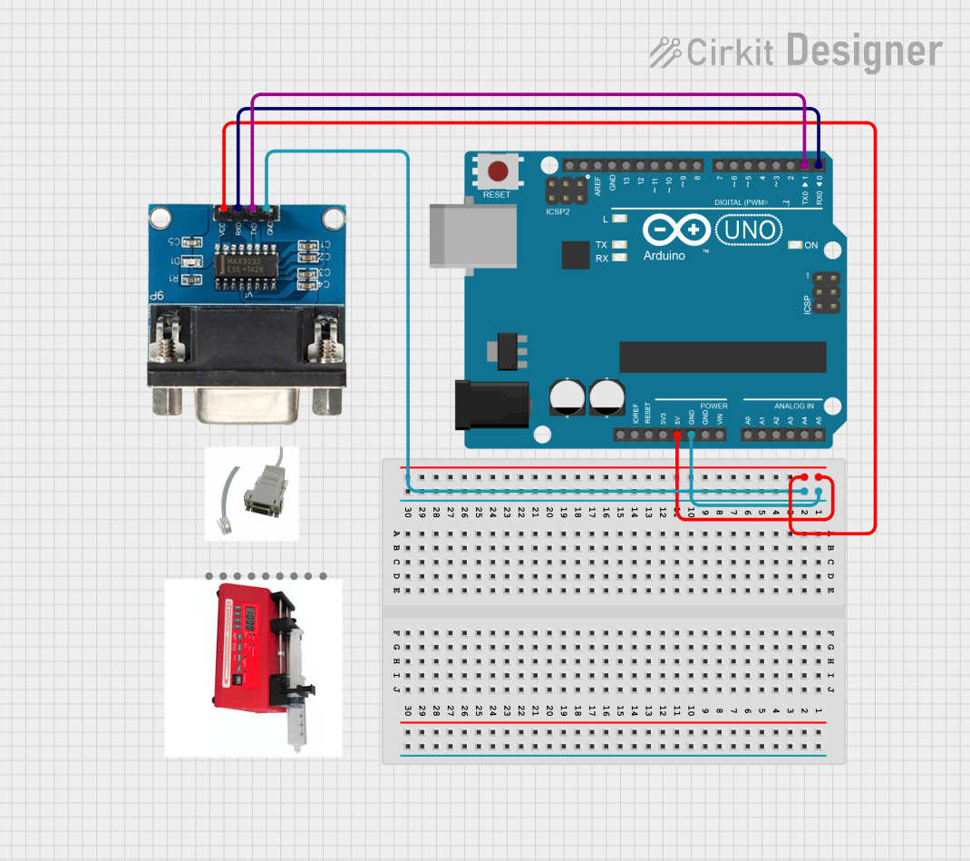
Example: Connecting to an Arduino UNO (TTL UART)
Below is an example of how to connect the USB to Multi-Protocol Serial Cable to an Arduino UNO for serial communication:
Wiring
| Cable Wire | Arduino Pin |
|---|---|
| Black (GND) | GND |
| White (TXD) | RX (Pin 0) |
| Green (RXD) | TX (Pin 1) |
Arduino Code
// Example code for testing serial communication with the USB to Multi-Protocol Serial Cable
void setup() {
  Serial.begin(9600); // Initialize serial communication at 9600 baud
  Serial.println("Serial communication test started.");
}

void loop() {
  if (Serial.available() > 0) {
    // Read incoming data from the USB to Serial Cable
    char received = Serial.read();
    // Echo the received data back to the sender
    Serial.print("Received: ");
    Serial.println(received);
  }
}
Troubleshooting and FAQs
Common Issues and Solutions
No Data Transmission
- Cause: Incorrect wiring or protocol selection.
- Solution: Double-check the wiring and ensure the correct protocol is being used.
Device Not Recognized
- Cause: Missing or incorrect drivers.
- Solution: Install the appropriate drivers for your operating system.
Data Corruption
- Cause: Mismatched baud rate or serial settings.
- Solution: Verify that the baud rate, parity, and stop bits match between the cable and the connected device.
RS-485 Communication Issues
- Cause: Missing termination resistors or incorrect A/B wiring.
- Solution: Add 120-ohm termination resistors at both ends of the RS-485 bus and verify the A/B connections.
FAQs
Q: Can I use this cable with a Raspberry Pi?
- A: Yes, the cable can be used with a Raspberry Pi for TTL UART communication. Connect the TXD, RXD, and GND wires to the corresponding GPIO pins.
Q: Does this cable support 1.8V logic levels?
- A: No, the cable only supports 3.3V and 5V logic levels for TTL UART.
Q: Can I use this cable for simultaneous RS-232 and RS-485 communication?
- A: No, the cable is designed to support one protocol at a time.
Q: Is the cable compatible with macOS Ventura?
- A: Yes, the cable is compatible with macOS Ventura, but you may need to install drivers depending on the chipset.
This documentation provides a comprehensive guide to using the Adafruit USB to Multi-Protocol Serial Cable effectively. For further assistance, refer to the Adafruit support resources.