
How to Use USB power: Examples, Pinouts, and Specs
 Design with USB power in Cirkit Designer
Introduction
USB power is a standard interface for supplying power to electronic devices. It typically provides a regulated 5V DC output from a USB port, making it a versatile and widely used power source. USB power is commonly utilized for charging devices such as smartphones, tablets, and wearables, as well as powering small electronic circuits, development boards, and IoT devices.
Explore Projects Built with USB power
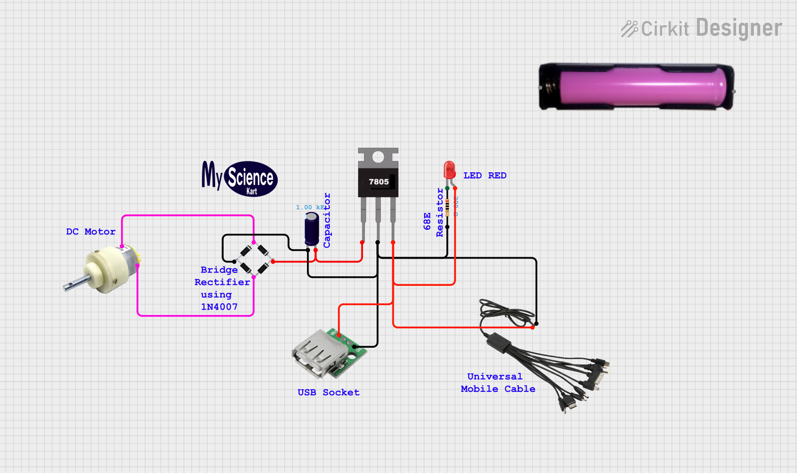 Open Project in Cirkit Designer
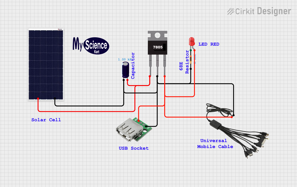 Open Project in Cirkit Designer
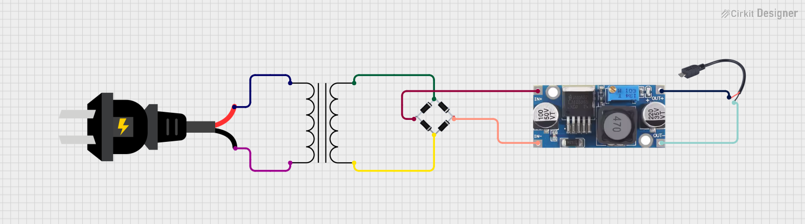 Open Project in Cirkit Designer
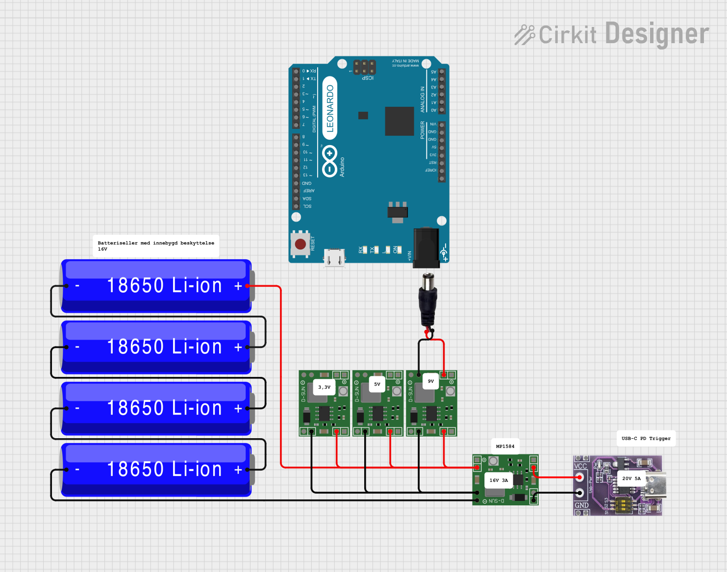 Open Project in Cirkit Designer
Explore Projects Built with USB power
Open Project in Cirkit DesignerOpen Project in Cirkit DesignerOpen Project in Cirkit DesignerOpen Project in Cirkit DesignerCommon Applications and Use Cases
- Charging portable devices (e.g., phones, tablets, power banks)
- Powering microcontroller boards (e.g., Arduino, Raspberry Pi)
- Supplying power to small electronic circuits and sensors
- Providing a portable power source for prototyping and testing
Technical Specifications
Below are the key technical details for USB power:
| Parameter | Specification |
|---|---|
| Voltage Output | 5V DC (±5%) |
| Current Output | Typically 500mA to 3A (depending on USB type) |
| Power Output | Up to 15W (USB Type-C supports higher) |
| Connector Types | USB-A, USB-B, Micro-USB, USB-C |
| Protection Features | Overcurrent, overvoltage, and short-circuit protection |
Pin Configuration and Descriptions
The USB connector has four or more pins, depending on the type. Below is the pinout for the most common USB connectors:
USB-A Connector Pinout
| Pin Number | Name | Description |
|---|---|---|
| 1 | VBUS (+5V) | Power supply (5V DC) |
| 2 | D- | Data line (-) |
| 3 | D+ | Data line (+) |
| 4 | GND | Ground |
USB-C Connector Pinout (Simplified Power Pins)
| Pin Number | Name | Description |
|---|---|---|
| A1, B1 | GND | Ground |
| A4, B4 | VBUS (+5V) | Power supply (5V DC) |
| A5, B5 | CC1, CC2 | Configuration channel (negotiates power) |
Usage Instructions
How to Use USB Power in a Circuit
- Connect the USB Power Source: Use a USB cable to connect the USB power source (e.g., a USB wall adapter, power bank, or computer USB port) to your device or circuit.
- Verify Voltage and Current Requirements: Ensure that the device or circuit being powered is compatible with the 5V output and does not exceed the current rating of the USB power source.
- Use Voltage Regulators if Necessary: If your circuit requires a voltage other than 5V, use a voltage regulator or DC-DC converter to step up or step down the voltage.
- Protect Your Circuit: Add components such as fuses, diodes, or capacitors to protect against overcurrent, reverse polarity, or voltage spikes.
Important Considerations and Best Practices
- Avoid Overloading: Do not connect devices that draw more current than the USB power source can supply. This may cause the source to shut down or overheat.
- Use Quality Cables: Low-quality USB cables may have high resistance, leading to voltage drops and reduced performance.
- Check for USB Standards: Ensure compatibility with USB 2.0, 3.0, or USB-C standards, depending on your application.
- Powering Microcontrollers: When using USB power with microcontroller boards like Arduino UNO, ensure the board's onboard voltage regulator can handle the input.
Example: Powering an Arduino UNO with USB Power
The Arduino UNO can be powered directly via its USB port. Below is an example of how to blink an LED using USB power:
// This example demonstrates how to blink an LED on pin 13
// The Arduino UNO is powered via USB (5V DC)

// Define the LED pin
const int ledPin = 13;

void setup() {
  pinMode(ledPin, OUTPUT); // Set pin 13 as an output
}

void loop() {
  digitalWrite(ledPin, HIGH); // Turn the LED on
  delay(1000);                // Wait for 1 second
  digitalWrite(ledPin, LOW);  // Turn the LED off
  delay(1000);                // Wait for 1 second
}
Troubleshooting and FAQs
Common Issues
Device Not Powering On
- Cause: Insufficient current from the USB power source.
- Solution: Use a higher-rated USB power adapter or check for faulty cables.
Voltage Drop
- Cause: Long or low-quality USB cables causing resistance.
- Solution: Use shorter, high-quality cables with thicker wires.
Overheating
- Cause: Overloading the USB power source.
- Solution: Reduce the load or use a power source with a higher current rating.
Interference with Data Lines
- Cause: Noise or improper grounding in the circuit.
- Solution: Use proper shielding and grounding techniques.
FAQs
Q: Can I use USB power to charge a 3.7V Li-ion battery?
A: No, USB power provides 5V, which is too high for direct charging of a 3.7V Li-ion battery. Use a dedicated Li-ion battery charging module (e.g., TP4056) to safely charge the battery.
Q: What is the maximum current I can draw from a USB port?
A: It depends on the USB standard:
- USB 2.0: Up to 500mA
- USB 3.0: Up to 900mA
- USB-C: Up to 3A (or higher with Power Delivery)
Q: Can I power multiple devices from a single USB port?
A: Yes, but ensure the total current draw does not exceed the USB port's maximum current rating. Use a powered USB hub if necessary.
Q: Is USB power safe for sensitive electronics?
A: Yes, USB power is generally safe, but adding protection components (e.g., diodes, capacitors) is recommended for sensitive circuits.