How to Use CD4518: Examples, Pinouts, and Specs
Introduction
The CD4518 is a dual 4-bit binary-coded decimal (BCD) up counter manufactured by Motorola. It is designed to count in binary up to 15 (1111 in binary) and features a reset function for clearing the count. The CD4518 is highly versatile and can be cascaded with other counters to extend its counting range. It operates over a wide voltage range, making it suitable for a variety of digital applications.
Explore Projects Built with CD4518


Explore Projects Built with CD4518
Common Applications and Use Cases
- Digital clocks and timers
- Frequency division and counting
- Event counting in digital systems
- Sequential logic circuits
- Cascaded counting for extended range applications
Technical Specifications
The following are the key technical details of the CD4518:
| Parameter | Value |
|---|---|
| Supply Voltage (VDD) | 3V to 15V |
| Input Voltage Range | 0V to VDD |
| Maximum Clock Frequency | 6 MHz (at 10V supply) |
| Output Voltage (High) | VDD - 0.05V (typical) |
| Output Voltage (Low) | 0.05V (typical) |
| Propagation Delay | 200 ns (at 10V supply) |
| Power Dissipation | 500 mW |
| Operating Temperature Range | -55°C to +125°C |
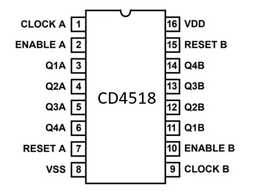
Pin Configuration and Descriptions
The CD4518 is a 16-pin dual in-line package (DIP). Below is the pinout and description:
| Pin Number | Pin Name | Description |
|---|---|---|
| 1 | MR1 | Master Reset for Counter 1 (Active High) |
| 2 | CP1 | Clock Input for Counter 1 |
| 3 | Q1A | Counter 1 Output A (Least Significant Bit) |
| 4 | Q1B | Counter 1 Output B |
| 5 | Q1C | Counter 1 Output C |
| 6 | Q1D | Counter 1 Output D (Most Significant Bit) |
| 7 | VSS | Ground (0V) |
| 8 | Q2D | Counter 2 Output D (Most Significant Bit) |
| 9 | Q2C | Counter 2 Output C |
| 10 | Q2B | Counter 2 Output B |
| 11 | Q2A | Counter 2 Output A (Least Significant Bit) |
| 12 | CP2 | Clock Input for Counter 2 |
| 13 | MR2 | Master Reset for Counter 2 (Active High) |
| 14 | VDD | Positive Supply Voltage |
| 15 | NC | No Connection |
| 16 | NC | No Connection |
Usage Instructions
How to Use the CD4518 in a Circuit
- Power Supply: Connect the VDD pin (Pin 14) to a positive voltage source (3V to 15V) and the VSS pin (Pin 7) to ground.
- Clock Input: Provide a clock signal to the CP1 (Pin 2) and/or CP2 (Pin 12) pins. Each clock pulse increments the respective counter.
- Reset Function: To reset a counter, apply a HIGH signal to the MR1 (Pin 1) or MR2 (Pin 13) pins. This clears the count to 0000.
- Outputs: The outputs (QxA, QxB, QxC, QxD) represent the binary count. Connect these pins to other digital components as needed.
- Cascading Counters: To extend the counting range, connect the most significant bit (MSB) output of one counter to the clock input of another CD4518.
Important Considerations and Best Practices
- Debounce the Clock Signal: If using a mechanical switch for the clock input, ensure the signal is debounced to avoid erratic counting.
- Avoid Floating Inputs: Unused inputs should be tied to a defined logic level (HIGH or LOW) to prevent unpredictable behavior.
- Voltage Compatibility: Ensure that the input and output voltage levels are compatible with other components in the circuit.
- Bypass Capacitor: Place a 0.1 µF ceramic capacitor close to the VDD pin to reduce noise and improve stability.
Example: Using CD4518 with Arduino UNO
The following example demonstrates how to use the CD4518 with an Arduino UNO to count clock pulses and display the count on the serial monitor.
// CD4518 Example with Arduino UNO
// Connect CP1 (Pin 2) to Arduino Pin 3 for clock signal
// Connect Q1A, Q1B, Q1C, Q1D (Pins 3, 4, 5, 6) to Arduino Pins 8, 9, 10, 11

const int clockPin = 3; // Arduino pin connected to CP1
const int outputPins[] = {8, 9, 10, 11}; // Q1A, Q1B, Q1C, Q1D

void setup() {
  pinMode(clockPin, OUTPUT); // Set clock pin as output
  for (int i = 0; i < 4; i++) {
    pinMode(outputPins[i], INPUT); // Set output pins as input
  }
  Serial.begin(9600); // Initialize serial communication
}

void loop() {
  // Generate a clock pulse
  digitalWrite(clockPin, HIGH);
  delay(100); // 100 ms HIGH pulse
  digitalWrite(clockPin, LOW);
  delay(100); // 100 ms LOW pulse

  // Read the counter outputs
  int count = 0;
  for (int i = 0; i < 4; i++) {
    count |= digitalRead(outputPins[i]) << i; // Combine bits into a single number
  }

  // Print the count to the serial monitor
  Serial.print("Count: ");
  Serial.println(count);
}
Troubleshooting and FAQs
Common Issues and Solutions
Counter Not Incrementing:
- Ensure the clock signal is properly connected and toggling between HIGH and LOW.
- Verify that the MR1 or MR2 pins are not held HIGH, as this will continuously reset the counter.
Erratic Counting:
- Check for noise or bouncing on the clock signal. Use a debounce circuit or software debounce if necessary.
- Ensure all unused inputs are tied to a defined logic level.
Incorrect Output:
- Verify the connections to the output pins (QxA, QxB, QxC, QxD).
- Ensure the supply voltage is within the specified range.
FAQs
Q: Can I use the CD4518 with a 5V power supply?
A: Yes, the CD4518 operates within a wide voltage range of 3V to 15V, so it is compatible with a 5V supply.
Q: How do I cascade multiple CD4518 counters?
A: Connect the MSB output (QxD) of one counter to the clock input (CPx) of the next counter. This allows the second counter to increment after the first counter completes a full cycle.
Q: What is the maximum counting range of a single CD4518?
A: Each counter in the CD4518 can count from 0 to 15 (4 bits). Since it is a dual counter, the total counting range is 0 to 15 for each counter.