How to Use SparkFun Qwiic Twist - RGB Rotary Encoder Breakout: Examples, Pinouts, and Specs
Introduction
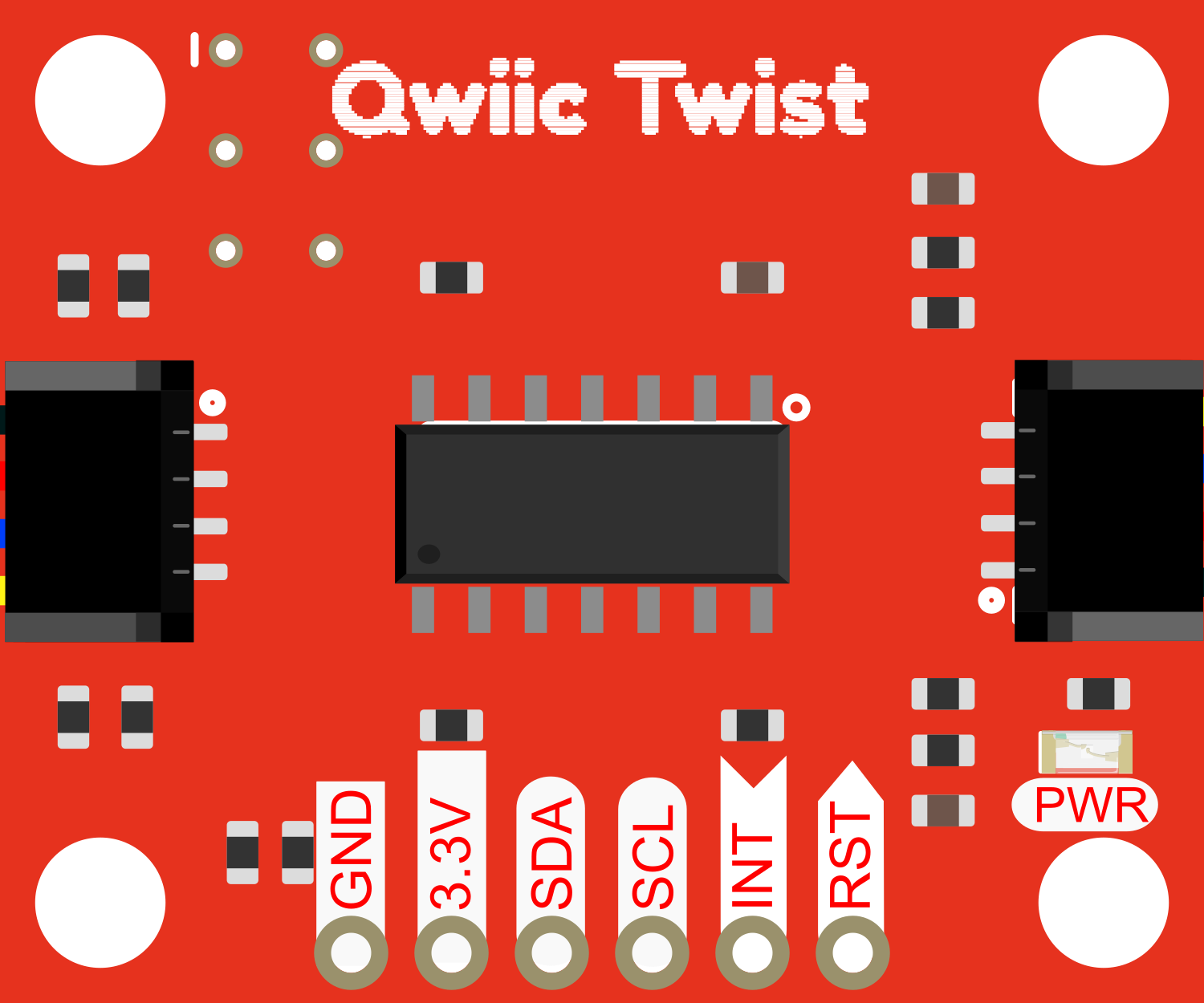
The SparkFun Qwiic Twist is an innovative rotary encoder breakout that simplifies the addition of a rotary knob to your projects. It features an RGB LED ring and an end-stop-less turning encoder, allowing for an infinite number of rotations in either direction. This component is ideal for user input applications such as adjusting volume, scrolling through menus, or changing settings. The Qwiic Twist is designed to be easily integrated into projects with SparkFun's Qwiic connect system, eliminating the need for soldering.
Explore Projects Built with SparkFun Qwiic Twist - RGB Rotary Encoder Breakout
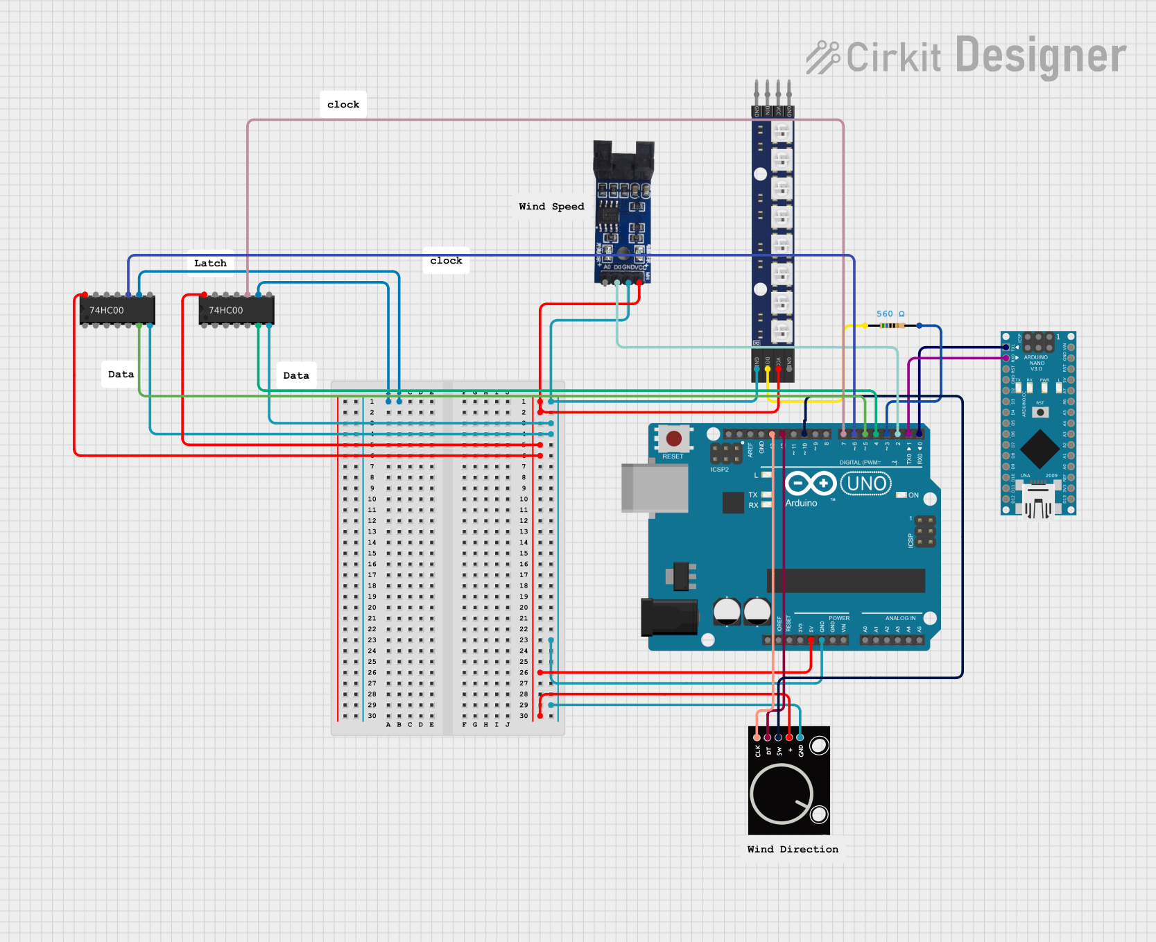
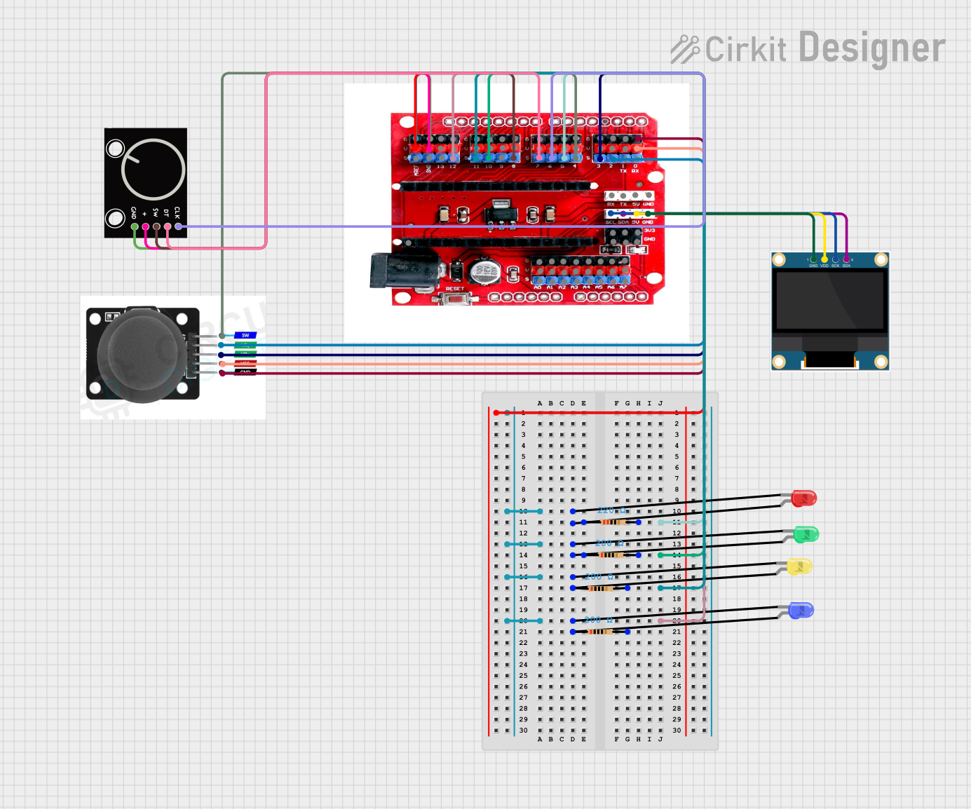
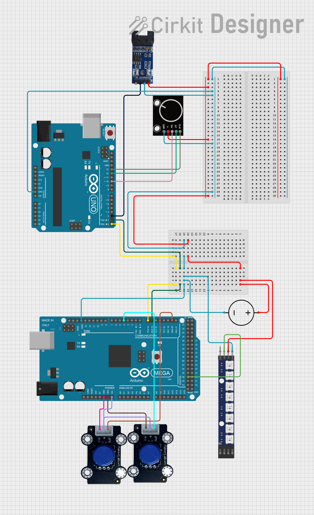
Explore Projects Built with SparkFun Qwiic Twist - RGB Rotary Encoder Breakout
Common Applications
- User interface controls
- Volume knobs
- Menu selectors
- Lighting controls
- Interactive art installations
Technical Specifications
Key Technical Details
- Voltage: 3.3V (via Qwiic connect system)
- Current: 10 mA (no LEDs), 30 mA (all LEDs on)
- Output: I2C (up to 400kHz)
- Encoder Resolution: 24 pulses per rotation
- LEDs: 12x RGB LEDs, individually addressable
Pin Configuration and Descriptions
| Pin Name | Description |
|---|---|
| 3.3V | Power supply input (3.3V from Qwiic system) |
| GND | Ground connection |
| SDA | I2C data line |
| SCL | I2C clock line |
| INT | Interrupt pin (active low) |
Usage Instructions
Integration with a Circuit
- Connect the Qwiic Twist to your microcontroller or development board using a Qwiic cable.
- Ensure that your board operates at 3.3V to match the Qwiic system's voltage level.
- If not using a Qwiic-enabled board, you can connect the SDA and SCL pins to your board's I2C bus, and the INT pin if interrupt functionality is required.
Important Considerations and Best Practices
- Avoid applying more than 3.3V to the Qwiic Twist to prevent damage.
- When handling the device, be cautious of electrostatic discharge (ESD).
- Ensure that the I2C bus has pull-up resistors, as they are typically not included on the Qwiic Twist board.
- The RGB LEDs can draw significant current; ensure your power supply can handle the load if all LEDs are on.
Example Code for Arduino UNO
#include <Wire.h>
#include <SparkFun_Qwiic_Twist_Arduino_Library.h> // Include the Qwiic Twist library

TWIST myTwist; // Create instance

void setup() {
  Wire.begin(); // Join I2C bus
  Serial.begin(9600); // Start serial for output

  if (myTwist.begin() == false) {
    Serial.println("Qwiic Twist not detected. Check connections.");
    while (1);
  }

  myTwist.setCount(0); // Reset encoder count to 0
  myTwist.connectRed(255); // Set red color max
  myTwist.connectGreen(0); // Set green color off
  myTwist.connectBlue(0); // Set blue color off
}

void loop() {
  if (myTwist.isPressed()) {
    Serial.println("Button pressed!");
  }

  int16_t count = myTwist.getCount(); // Get the current count
  Serial.print("Count: ");
  Serial.println(count);

  delay(100); // Add delay for debounce
}
Code Comments
#includestatements are used to include the necessary libraries for the Qwiic Twist.TWIST myTwist;creates an object for the rotary encoder.Wire.begin();initializes the I2C bus.Serial.begin(9600);starts serial communication for debugging purposes.myTwist.begin()initializes the Qwiic Twist and checks for its presence.myTwist.setCount(0);resets the encoder's count to zero.myTwist.connectRed(255);,.connectGreen(0);, and.connectBlue(0);set the initial color of the RGB LED ring.myTwist.isPressed()checks if the encoder's button is pressed.myTwist.getCount()retrieves the current position count of the encoder.delay(100);is used to debounce the button press.
Troubleshooting and FAQs
Common Issues
- Encoder not responding: Ensure that the Qwiic Twist is properly connected and that the I2C bus is operational.
- LEDs not lighting up: Check the power supply and ensure that the LED control code is correctly implemented.
- Inaccurate count: Verify that the encoder is not experiencing mechanical issues and that the code is correctly reading the count.
Solutions and Tips for Troubleshooting
- Double-check all connections and ensure that the Qwiic cable is fully seated.
- Use the
Serial.println()function to debug and verify that the encoder is communicating over the I2C bus. - If using the interrupt pin, ensure that it is configured correctly in your microcontroller's firmware.
FAQs
Q: Can I use the Qwiic Twist with a 5V system? A: While the Qwiic Twist is designed for 3.3V systems, it may be possible to use it with a 5V system by using a logic level converter for the I2C lines.
Q: How do I change the color of the LEDs?
A: Use the connectRed(), connectGreen(), and connectBlue() functions to set the color of the LEDs.
Q: What is the maximum I2C speed the Qwiic Twist supports? A: The Qwiic Twist supports I2C speeds up to 400kHz.
Q: Can I use multiple Qwiic Twists on the same I2C bus? A: Yes, each Qwiic Twist has a unique I2C address that can be changed using solder jumpers on the back of the PCB, allowing multiple devices on the same bus.